You are using EBGP to connect to two upstream peers in the same AS. You want to make one of the links less preferred for traffic entering your network from the peer's AS. Which feature should you use to achieve this goal?
a route reflector
origin code
AS-path prepending
local preference
In the world of BGP, controllinginbound traffic(traffic entering your network) is significantly more challenging than controlling outbound traffic because it requires influencing a decision made by an external Autonomous System (AS). According to Juniper Networks documentation, when you have multiple links to the same AS or even different ASes, the BGP path selection process is used by the upstream neighbor to decide which path to take to reach your prefixes.
AS-Path Prependingis the standard technique used to make a path appear less attractive to external peers. By artificially lengthening the AS_PATH attribute on the BGP advertisements sent over a specific link, you exploit the BGP best-path algorithm rule that prefers a shorter AS path. When you prepend your own AS number multiple times to the update sent to the "less preferred" peer, that peer’s BGP routers will see a longer path compared to the alternative link and will naturally prefer the shorter, unprepended route.
It is important to distinguish why other options are incorrect for this specific goal:
Local Preference (Option D):This is a well-known discretionary attribute used to influenceoutboundtraffic. It is not advertised to EBGP peers; therefore, your upstream neighbor cannot see your local preference settings.
Origin Code (Option B):While the origin code (IGP, EGP, or Incomplete) is a tie-breaker in the selection process, it is rarely used for traffic engineering and lacks the granular control provided by prepending.
Route Reflector (Option A):This is an Internal BGP (IBGP) scaling mechanism used to reduce the need for a full mesh of peers within an AS; it does not directly influence external path selection by an upstream provider.
Junos OS allows you to easily implement prepending viarouting policiesapplied as an "export" policy to the EBGP neighbor. By using the as-path-prepend action within a policy term, you can selectively degrade a path's attractiveness to manage your inbound bandwidth.
Which two statements about graceful restart are correct? (Choose two.)
Graceful restart restarting router mode is not enabled by default.
Graceful restart helper mode is enabled by default.
Graceful restart requires that GRES be enabled.
Graceful restart uses nonstop bridging for forwarding operations.
Graceful Restart (GR)is a high-availability mechanism designed to minimize the impact of a routing protocol process (rpd) restart or a Routing Engine (RE) switchover. It allows a router to continue forwarding traffic while the control plane is recovering, provided that the data plane (Packet Forwarding Engine) remains intact.
According to Juniper Networks documentation, Graceful Restart operates in two distinct roles:
Restarting Mode:This is the role of the router that is actually undergoing the restart. In Junos OS, this mode isnot enabled by default (Option A). An administrator must explicitly configure graceful-restart under the [edit routing-options] hierarchy to allow the router to signal its neighbors that it is attempting a graceful recovery.
Helper Mode:This is the role of the neighboring routers. When a neighbor sees a router restart, if it is in "helper mode," it will continue to forward traffic toward the restarting router and will not flush the associated routes from its forwarding table for a specified period. In Junos,helper mode is enabled by default (Option B)for most protocols (OSPF, BGP, IS-IS). This means that even if you haven't configured GR on your own router, it will automatically assist its neighbors if they perform a graceful restart.
Why other options are incorrect:
Option C:WhileGRES (Graceful Routing Engine Switchover)is often usedwithGraceful Restart to handle hardware-level RE failures, they are independent features. GR can function during a simple software process restart without dual REs or GRES.
Option D:Nonstop Bridging (NSB)is a separate high-availability feature for Layer 2 protocols (like STP). While it shares a similar goal, Graceful Restart is specifically a Layer 3 protocol mechanism (Layer 2 does not use "helper" routers in the same way).
You must ensure that your routing platform with redundant REs continues to forward packets, even if one RE fails. Which technology would you use to accomplish this task?
NSB
LAG
BFD
GRES
For Juniper platforms equipped with dualRouting Engines (REs), the fundamental technology required to provide high availability during a hardware or software failure of the primary RE isGraceful Routing Engine Switchover (GRES).
According to Juniper Networks technical documentation, GRES allows the backup RE to stay in a "hot" standby state. When GRES is enabled, the primary RE synchronizes critical state information with the backup RE, specifically thechassis stateand theinterface state. This synchronization includes the Packet Forwarding Engine (PFE) configuration.
When the primary RE fails, the backup RE takes over immediately. Because the PFE (which resides on the line cards) was already synchronized and is not restarted during the switchover, the routercontinues to forward packetsthat are already in flight or part of established flows. This prevents a complete network outage during an RE failover.
Comparison with other options:
NSB (Non-Stop Bridging - Option A):Focuses specifically on maintaining Layer 2 protocol states (like STP) during a switchover.
LAG (Link Aggregation - Option B):Provides redundancy for physical links, not the control plane or the RE.
BFD (Bidirectional Forwarding Detection - Option C):Is a protocol used for rapid detection of link or neighbor failures; it does not protect the RE or maintain forwarding during an internal switchover.
It is important to note that while GRES maintains theforwardingstate, it does not by itself maintain therouting protocolstate (adjacencies). To keep OSPF or BGP sessions from dropping during the switchover, GRES must be paired withNon-Stop Active Routing (NSR). However, as the question focuses on the core requirement of continuing to forward packets,GRESis the foundational technology.
Which two statements are correct about TLVs in IS-IS? (Choose two.)
LSPs can only contain one TLV.
TLVs only support encoding IPv4 routing information.
TLVs allow flexible encoding of routing information.
LSPs can contain multiple TLVs.
In the IS-IS protocol,TLVs (Type, Length, Value)are the fundamental building blocks used to carry information withinLink-State PDUs (LSPs). Unlike some other protocols that have a fixed, rigid packet format, IS-IS was designed from the ground up to be modular and extensible. This extensibility is achieved through the use of TLVs, which allow the protocol to carry different types of data without requiring changes to the core protocol state machine.
According to Juniper Networks technical documentation,TLVs allow flexible encoding of routing information (Option C). Each TLV specifies the "Type" of information it carries (such as neighbor information or IP reachability), the "Length" of that information, and the "Value" (the actual data). This architecture is what allowed IS-IS to easily support IPv6 by simply adding new TLVs (like TLV 236 for IPv6 reachability) without redesigning the protocol. It also supports Traffic Engineering (TE) extensions used in MPLS environments by adding TLVs that describe link bandwidth and administrative groups.
Furthermore, a singleLSP can contain multiple TLVs (Option D). When a Juniper router generates an LSP, it packs all the necessary information—such as the router's area addresses, its neighbors, and its local interface prefixes—into various TLVs and places them into a single PDU. If the amount of information exceeds the Maximum Transmission Unit (MTU) of the interface, the router will generate additional LSPs (fragmented LSPs) to carry the remaining TLVs.
Options A and B are incorrect because restricting an LSP to a single TLV would make the protocol incredibly inefficient, and the very nature of IS-IS is its ability to support multiple network layer protocols (not just IPv4) through its agnostic TLV-based transport.
Exhibit:

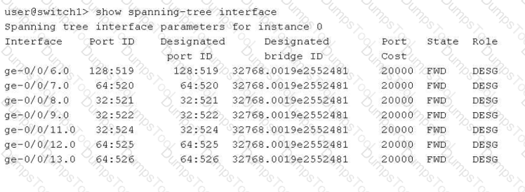
Referring to the exhibit, which two statements are correct? (Choose two.)
The switch1 device is using VSTP.
The switch1 device is the root bridge.
The ge-0/0/8, ge-0/0/9, and ge-0/0/11 interfaces are using the default interface priority.
The bridge priority for switch1 is 32k.
In the provided exhibit, the output of the command show spanning-tree interface for switch1 reveals critical details about the Spanning Tree Protocol (STP) operational state.
The first correct statement is thatthe switch1 device is the root bridge(Option B). This is determined by comparing the "Port ID" column with the "Designated port ID" column, as well as checking the "Designated bridge ID". In the exhibit, for every interface listed (from ge-0/0/6.0 to ge-0/0/13.0), the Port ID and the Designated port ID are identical. Furthermore, every port is in the "FWD" (Forwarding) state with the "DESG" (Designated) role. In a Spanning Tree topology, the root bridge is the only device where all active participating interfaces serve as designated ports, as it has no need for a "Root" port role (which points toward a root bridge).
The second correct statement is thatthe bridge priority for switch1 is 32k(Option D). Looking at the "Designated bridge ID" column, we see the value 32768.0019e2552481. In Junos and general networking standards, the Bridge ID is composed of a bridge priority and the device's MAC address. The default priority for most Spanning Tree variants (STP, RSTP, MSTP) is 32,768, which is commonly referred to in shorthand as "32k".
Regarding the incorrect options:
Option A:There is no evidence of VSTP (VLAN Spanning Tree Protocol); the output shows "instance 0," which is typical for IEEE standard RSTP or STP.
Option C:The Port IDs for ge-0/0/8, ge-0/0/9, and ge-0/0/11 all start with "32" (e.g., 32:521), whereas the default port priority is typically 128 (as seen in ge-0/0/6.0 with 128:519). This indicates that the interface priorities for these specific ports have been manually tuned to a non-default value.
Exhibit:

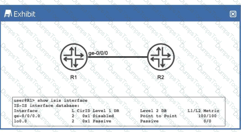
Referring to the exhibit, R1 and R2 are configured to run IS-IS. The IS-IS adjacency between R1 and R2 is up. What does the output of the show isis interface command tell you about R1?
R1 is not configured to use wide metrics.
R1 only forms a Level 2 adjacency with R2.
R1 advertises a Level 1 metric of 100 and a Level 2 metric of 100 toward R2 in its link-state PDU.
R1 sends Level 1 hello PDUs to R2.
In theIS-IS (Intermediate System to Intermediate System)protocol as implemented in Junos OS, routers can operate at two hierarchical levels:Level 1 (L1)for intra-area routing andLevel 2 (L2)for inter-area backbone routing. By default, a Juniper router and its interfaces are configured to act asLevel 1/2, meaning they will attempt to form adjacencies at both levels simultaneously.
According to Juniper Networks technical documentation, the show isis interface command provides a granular view of how the protocol is interacting with specific local links. In the provided exhibit, we must examine theL (Level)column and theDR (Designated Router)status columns to understand R1's operational state.
Level Configuration:Under the L column for both the physical interface ge-0/0/0.0 and the loopback lo0.0, the value is strictly2. This indicates that these interfaces have been explicitly configured to operate only at Level 2.
Adjacency Capabilities:For the interface ge-0/0/0.0, the Level 1 DR field is marked asDisabled. This confirms that R1 is not participating in Level 1 operations on this link; it will not transmit Level 1 Hello PDUs, nor will it listen for them. Consequently, R1 is incapable of forming a Level 1 adjacency with R2 on this segment.
Metric Implications:The exhibit shows an L1/L2 Metric of100/100. In Junos, "narrow" metrics (the default) are limited to a maximum value of 63 per interface. A metric of 100 indicates thatwide metrics(wide-metrics-only) have been enabled. Therefore, option A is incorrect because the routerisusing wide metrics.
Since the prompt states the adjacency is "up," and the interface is restricted to Level 2, we can conclude thatR1 only forms a Level 2 adjacency with R2 (Option B). Even though an L1 metric of 100 is displayed in the table as a configured value, it is not actually "advertised" in a Link-State PDU because the Level 1 protocol is disabled on that interface.
How are routing loops prevented in external BGP networks?
By default, a router receiving a route with its own AS in the AS Path attribute will use the route.
Routing policies must be used to drop looped routes.
Routing policies must be used to accept valid routes.
By default, a router receiving a route with its own AS in the AS Path attribute will not use the route.
BGP is apath-vector protocol, and its primary mechanism for ensuring a loop-free topology across the global internet is theAS_PATHattribute. This attribute is a "well-known mandatory" attribute that records every Autonomous System (AS) a prefix has passed through.
According to Juniper Networks Service Provider documentation, the loop prevention rule forExternal BGP (EBGP)is straightforward: when a router receives a BGP Update from an EBGP peer, it examines the AS_PATH list. If the router's ownlocal AS numberis already present in the list, it indicates that the advertisement has already traversed the local AS and has returned. To prevent a routing loop, the routerwill not use the routeand will implicitly discard the update (Option D).
This behavior is a default, hard-coded function of the BGP protocol and does not require the administrator to write manualrouting policies(Options B and C) to achieve basic loop prevention. While there are advanced features like as-path-expand or allow-as-in that can modify this behavior for specific design requirements (such as in certain Hub-and-Spoke MPLS VPN topologies), the standard operational default is to reject any route where the local AS is detected in the path. This ensures that traffic does not circulate infinitely between Autonomous Systems.
Exhibit:

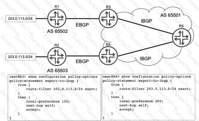
Referring to the exhibit, R1 and R2 are advertising the same prefix 203.0.113.0/24 to R3 and R4 over EBGP. R3 and R4 both advertise this prefix to R5. Which advertisement does R5 choose to install in its routing table?
The advertisement from R4 is chosen.
The advertisements from both R3 and R4, but R3 is chosen for forwarding.
The advertisement from R3 is chosen.
The advertisements from both R3 and R4, but R4 is chosen for forwarding.
In a Juniper Networks environment, when a router receives multiple BGP paths for the same destination prefix, it utilizes theBGP Path Selection Algorithmto determine the single "best" path to install in the routing table and advertise to other peers. This selection process follows a strict hierarchy of attributes.
According to Juniper Networks technical documentation, the very first attribute evaluated by the BGP process (after ensuring the next hop is reachable) is theLocal Preference. Local preference is a well-known discretionary attribute used to communicate a preference for a specific exit point from the local Autonomous System (AS). A higher local preference value is always preferred over a lower one.
Analyzing the exhibit:
R3receives the prefix from R1 and applies an export policy to its IBGP session that sets thelocal preference to 150.
R4receives the same prefix from R2 and applies an export policy to its IBGP session that sets thelocal preference to 200.
R5receives both of these IBGP updates from R3 and R4.
When R5 runs the best-path algorithm for the 203.0.113.0/24 prefix, it compares the local preference values. Since the path from R4 has a local preference of 200 and the path from R3 has a local preference of 150, R5 immediately selects the path fromR4as the best route. Because BGP is designed to prevent loops and maintain a consistent view, only this single best path is installed as the active route in R5's routing table (inet.0). Options B and D are incorrect because they imply multiple paths are installed for forwarding, which only occurs if specific multipath load-balancing is configured, which is not indicated here.
Exhibit:
user@R10> show configuration protocols isis
interface ge-0/0/1.0 {
point-to-point;
}
interface ge-0/0/2.0 {
point-to-point;
}
interface lo0.0;
source-packet-routing {
srgb start-label 300000 index-range 10000;
}
level 1 disable;
level 2 wide-metrics-only;
reference-bandwidth 100g;
You have a network of ten routers that have all been configured with an identical SRGB. The exhibit shows the IS-IS configuration from a router called R10. The other nine routers do not yet have an IPv4 shortest-path SR-MPLS LSP to this router. Which missing part of the configuration must you add on R10 to solve this problem?
R10 must be configured with an explicit binding SID.
R10 must be configured with explicit IPv4 adjacency SID.
R10 must tag its internal IPv4 BGP prefixes with a BGP prefix SID.
R10 must be configured with an explicit IPv4 node SID.
In aSegment Routing (SR-MPLS)architecture using IS-IS as the control plane, routers exchange labels (segments) to build Label-Switched Paths (LSPs) without the need for traditional signaling protocols like LDP or RSVP. According to Juniper Networks technical documentation, for a router to be reachable via a shortest-path LSP from other nodes in the network, it must advertise aPrefix Segment Identifier (Prefix SID).
A specific type of Prefix SID is theNode SID, which is assigned to a loopback address (typically lo0.0) to uniquely identify the router within the SR domain. In the provided exhibit, routerR10has been configured with aSegment Routing Global Block (SRGB)starting at label 300000. This configuration tells the router which label range to use for global segments, but it does not automatically assign a label to its own loopback interface.
Without aNode SIDconfiguration, R10 is not telling its neighbors which specific index or label within that SRGB corresponds to its own address. Consequently, the other nine routers in the IS-IS area can calculate the shortest path to R10 using standard SPF, but they cannot perform the "label-binding" necessary to push an SR-MPLS label onto the packets.
To solve this, a Node SID must be explicitly configured under the loopback interface within the IS-IS protocol hierarchy, such as:
set protocols isis interface lo0.0 level 2 ipv4-node-sid index
Analysis of incorrect options:
Binding SID (Option A):This is used to encapsulate or steer traffic into a specific policy or tunnel (like a TE-LSP) and is not required for basic shortest-path reachability.
Adjacency SID (Option B):These are generated automatically by Junos for each link and represent a specific local hop; they are not used for global "shortest-path" forwarding to a distant node.
BGP Prefix SID (Option C):This is used for BGP Egress Peer Engineering (EPE) or prefix advertisement via BGP, which is not relevant for building the underlying IS-IS SR-MPLS transport.
Therefore, configuring anexplicit IPv4 node SIDis the mandatory step to enable the rest of the network to build a shortest-path SR-LSP toward R10.
You are the administrator for two Junos routers called R1 and R2. These two routers are directly connected to each other. These two routers run IS-IS and BFD. R1 is configured to send BFD packets every 300 milliseconds. R2 is configured to send BFD packets every 400 milliseconds. In this situation, what is the expected outcome?
Each router will send BFD packets at the rate that has been locally configured.
BFD will fail due to the mismatched timers.
Each router will negotiate to send BFD packets at the slowest of the two rates.
Each router will negotiate to send BFD packets at the fastest of the two rates.
In the context of Juniper Networks High Availability,Bidirectional Forwarding Detection (BFD)is a lightweight protocol designed to provide fast failure detection for the forwarding path. Unlike the slow "hello" mechanisms found in IGPs like OSPF or IS-IS, BFD can detect link or neighbor failures in sub-second intervals.
According to Juniper Networks technical documentation, BFD operates through a negotiation process. When two routers establish a BFD session, they exchange their locally configuredMinimum Transmit IntervalandMinimum Receive Intervalwithin the BFD control packets. The fundamental rule of BFD negotiation is that the routers must agree on a common timing value that accommodates the slower of the two devices to ensure stability and prevent "false positives" (detecting a failure when none exists simply because one router cannot keep up with the processing speed).
In this scenario, R1 expects to send at 300ms, while R2 is configured for 400ms. During the handshake, R1 informs R2 it is capable of 300ms, but R2 informs R1 it can only support a minimum of 400ms. Consequently, the routers will negotiate to use theslowest of the two rates (400ms). Specifically, the transmission interval of one router is matched to the receive interval of the other. By choosing the highest common denominator (the slowest rate), the BFD session ensures that both routers have sufficient time to process incoming control packets. This negotiation allows BFD to be highly flexible in heterogeneous environments where different hardware platforms may have varying CPU capabilities for handling rapid heartbeat packets.
Exhibit:

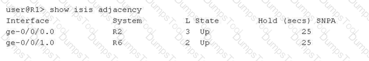
Referring to the exhibit, why is the ge-0/0/0.0 interface shown as belonging to Level 3?
This interface is configured as a point-to-point interface, that uses Level 3 as shorthand for both Level 1 and Level 2.
This interface is configured as a broadcast interface that has three adjacencies with other routers on the shared LAN.
This interface connects to a super spine.
This interface is configured as a broadcast interface, that uses Level 3 as shorthand for both Level 1 and Level 2.
In theIS-IS (Intermediate System to Intermediate System)protocol as implemented in Junos OS, the output of operational commands uses specific numerical representations to denote the hierarchy levels of a neighbor adjacency. Understanding these values is crucial for troubleshooting peering relationships in a multi-level IS-IS network.
According to Juniper Networks technical documentation, the show isis adjacency command displays the status of the neighbors. The "L" column indicates the level of the adjacency:
Level 1:Indicates the adjacency is strictly for intra-area routing.
Level 2:Indicates the adjacency is strictly for backbone/inter-area routing.
Level 3:This is ashorthand representationused by Junos to indicate that a single adjacency has been established forboth Level 1 and Level 2 simultaneously.
The critical distinction in this question lies in the interface type. On abroadcast interface(such as standard Ethernet), IS-IS typically establishes and maintains separate adjacencies for Level 1 and Level 2. In the CLI output for a broadcast link, you would generally see two separate lines for the same neighbor—one for Level 1 and one for Level 2.
However, on apoint-to-point (P2P)interface, IS-IS can negotiate both levels within a single adjacency. When this occurs, Junos consolidates the output into a single entry and usesLevel 3to signify that the adjacency is functional for both levels. Since the exhibit shows ge-0/0/0.0 as Level 3, it confirms that the link is configured with a point-to-point encapsulation (either natively or via the interface-type p2p command) and is acting as a Level 1/2 adjacency.
Option B is incorrect as the number "3" refers to protocol levels, not the count of neighbors. Option C is a reference to data center architectures that does not influence IS-IS level nomenclature. Option D is incorrect because, as noted, broadcast interfaces display these levels separately rather than using the Level 3 shorthand.
What information is determined by using the AS path attribute included in the BGP update message? (Choose two.)
the origin of a route from IGP or EGP
the presence of a routing loop
the shortest AS path to reach a prefix
the total number of next-hop devices to reach a prefix
TheAS_PATHattribute is a "well-known mandatory" attribute in BGP, meaning it must be present in every BGP Update message exchanged between External BGP (eBGP) peers. It records the sequence of Autonomous System numbers that a route has traversed. Per Juniper Networks Service Provider documentation, this attribute serves two fundamental purposes:
1. Loop Prevention (Option B):
This is the most critical function of the AS_PATH. When a BGP router receives an update from an eBGP peer, it scans the AS_PATH attribute for its own AS number. If the router finds its local AS number already listed in the path, it concludes that the route has already passed through its network and has "looped" back. To prevent an infinite routing loop, the router will immediately discard the update. This mechanism is the cornerstone of BGP's stability as a path-vector protocol.
2. Path Selection / Shortest Path Determination (Option C):
BGP uses a complex "tie-breaking" algorithm to select the best path among multiple candidates. One of the highest-ranking criteria in this algorithm (after Weight, Local Preference, and AS_PATH length) is the length of the AS_PATH. A shorter AS_PATH (fewer AS numbers listed) is generally preferred over a longer one, as it typically represents a more direct path through the internet hierarchy.
Why other options are incorrect:
Option A:The "origin" of a route (IGP, EGP, or Incomplete) is determined by theORIGINattribute, which is a separate well-known mandatory attribute.
Option D:BGP does not count individual "next-hop devices" (which would be an IGP metric like hop count in RIP); it only tracks Autonomous Systems. A single AS in the path might contain hundreds of internal routers (next-hops), but BGP only sees it as one "hop" in the AS_PATH.
Exhibit:
user@R2> show route 198.51.100.1
inet.0: 19 destinations, 19 routes (19 active, 0 holddown, 0 hidden)
Restart Complete
+ = Active Route, - = Last Active, * = Both
198.51.100.1/32 *[Static/5] 5d 21:02:26
> to 203.0.113.65 via ge-0/0/3.0
user@R2> show route 172.20.110.0/24
inet.0: 19 destinations, 19 routes (19 active, 0 holddown, 0 hidden)
Restart Complete
+ = Active Route, - = Last Active,
* = Both
172.20.110.0/24 *[Static/5] 10:43:01
> via gr-0/0/0.0
Referring to the exhibit, traffic destined to which network will be sent through the tunnel?
172.20.110.0/24
203.0.113.65
0.0.0.0/0
198.51.100.1/32
To determine which traffic is being sent through a tunnel in a Junos OS environment, an administrator must analyze the routing table output for the exit interface associated with each destination prefix. The provided exhibit shows the results of the show route command on routerR2for two specific destination networks.
In the first output, the destination198.51.100.1/32is an active static route. The next-hop information specifies that traffic for this address is sent to the gateway 203.0.113.65 via the interfacege-0/0/3.0. According to Juniper Networks interface naming conventions, the prefixge-denotes aGigabit Ethernetinterface, which represents a standard physical connection. Therefore, this traffic does not traverse a tunnel.
In the second output, the destination172.20.110.0/24is also an active static route. However, the next-hop for this network is listed asvia gr-0/0/0.0. In the Junos operating system, thegr-prefix explicitly identifies aGeneric Routing Encapsulation (GRE) tunnel interface. GRE is a widely used protocol in service provider networks to encapsulate various network layer protocols over an IP backbone, effectively creating a virtual point-to-point link. Because the routing table has installed the route for 172.20.110.0/24 specifically via the gr- interface, all traffic destined for this network will be encapsulated and sent through the tunnel.
The other choices are incorrect for the following reasons:
203.0.113.65 (Option B):This is the next-hop IP address for the physical Gigabit Ethernet path; it is not a destination network directed to a tunnel.
0.0.0.0/0 (Option C):There is no information in the exhibit regarding a default route.
198.51.100.1/32 (Option D):As identified by thege-interface prefix in the exhibit, traffic for this destination is sent via a physical Ethernet link.
Exhibit:

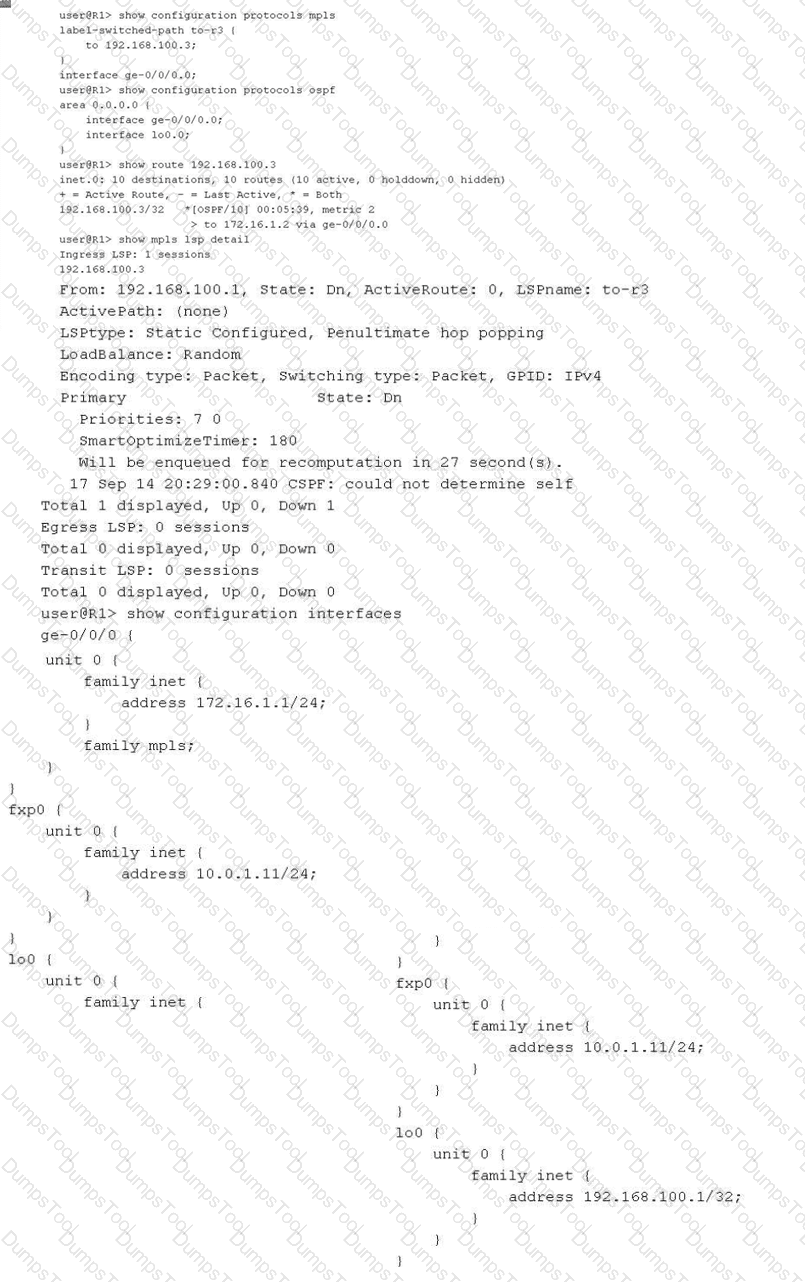
You have configured an MPLS LSP to 192.168.100.3. However, the LSP is in the down state. Referring to the exhibit, which two actions would solve this problem? (Choose two.)
Issue the set routing-options rib inet.3 static route 192.168.100.1 command and commit.
Issue the set protocols mpls label-switched-path to-r3 no-cspf command and commit.
Issue the set interfaces lo0 family mpls command on router R1 and commit.
Issue the set protocols ospf traffic-engineering command and commit.
In a Juniper Networks environment, establishing a functionalMultiprotocol Label Switching (MPLS)Label-Switched Path (LSP) requires synchronized control plane operations. According to Juniper technical documentation, the most common reason for an LSP to remain in the "Down" state at the ingress router is a failure of theConstrained Shortest Path First (CSPF)algorithm during the path computation phase.
The provided exhibit for routerR1reveals a critical error in the show mpls lsp detail output: "CSPF: could not determine self". This specific error indicates that the CSPF process is unable to find its own local router ID within theTraffic Engineering Database (TED). For CSPF to build a valid TED, the underlying Interior Gateway Protocol (IGP), such as OSPF, must be configured to flood opaque link-state advertisements (Type 10 LSAs) that carry traffic engineering attributes. As seen in the OSPF configuration, traffic engineering is not enabled. Therefore, issuing theset protocols ospf traffic-engineeringcommand (Option D) will allow R1 to populate the TED with its own local information and that of its neighbors, enabling CSPF to calculate a valid path.
Alternatively, an administrator can choose to bypass the requirement for a TED entirely by disabling CSPF on the specific LSP. By issuing theset protocols mpls label-switched-path to-r3 no-cspfcommand (Option B), the router will stop attempting to perform a constrained path calculation. Instead, the signaling protocol (RSVP) will rely on the standardinet.0routing table to determine the hop-by-hop path to the egress destination (192.168.100.3), allowing the LSP to establish without traffic engineering constraints.
Regarding the other options, whilefamily mplsis required on all transit interfaces, the ingress loopback interface (lo0) generally does not require it for standard LSP signaling unless it's used as a transit hop. Furthermore, adding a static route toinet.3(Option A) is used for next-hop resolution of BGP routes over LSPs but does not assist in the signaling or establishment of the LSP itself.
TESTED 24 Feb 2026
Copyright © 2014-2026 DumpsTool. All Rights Reserved