Which two actions are needed to advertise OSPF routes to BGP neighbors? Choose two.
Create a policy to match and accept the OSPF routes.
Apply the policy to the BGP group as an export policy.
Create a policy to match and accept the BGP routes.
Apply the policy to the BGP group as an import policy.
To advertise OSPF-learned routes to BGP neighbors on Junos, you must explicitly control route redistribution using policy. Junos does not automatically redistribute routes between routing protocols simply because both protocols are enabled. Instead, you create a routing policy that matches the routes you intend to export, in this case routes whose protocol origin is OSPF. The policy must accept those matched routes so they become eligible for advertisement.
After the policy is created, you must apply it as an export policy under the relevant BGP group or under the BGP protocol hierarchy, depending on your design. Export policy controls what your router sends to BGP peers. When the export policy accepts OSPF routes, Junos advertises those routes to the BGP neighbors in that group, subject to any additional BGP constraints such as next-hop handling, route families, and any peer-specific policy terms.
Creating a policy to match and accept BGP routes is not required for this goal because that would influence what routes are imported into your routing table from BGP, not what you export. Likewise, applying a policy as a BGP import policy affects received routes, not OSPF-to-BGP redistribution. In data center fabrics, this policy-driven approach prevents unintended route leakage and keeps redistribution tightly scoped to the prefixes that must be carried between domains.
Which statement is correct about the native VLAN ID feature? Choose one.
It restricts a trunk port to only send and receive tagged traffic.
It enables an access port to send and receive tagged traffic.
It restricts the usable VLAN IDs from 0 to 1024.
It enables trunk ports to send and receive untagged traffic.
In Junos Ethernet switching, a trunk interface is intended to carry multiple VLANs using 802.1Q tags. The native VLAN ID feature defines how the trunk handles frames that arrive without an 802.1Q tag and how it can transmit untagged frames when required. When a native VLAN is configured on a trunk, untagged inbound frames are mapped into the native VLAN’s Layer 2 broadcast domain. Likewise, traffic belonging to the native VLAN can be sent untagged on that trunk, depending on how the receiving device expects to process untagged frames. This is commonly used in data center environments to interoperate with devices that require one VLAN to be carried untagged, or for specific control-plane or legacy connectivity requirements.
Option A is incorrect because native VLAN does not restrict the trunk to tagged-only traffic; it explicitly provides a mechanism to accept or emit untagged frames on a trunk. Option B is incorrect because access ports are designed for a single VLAN and normally treat traffic as untagged by default; they do not become “tagged access” by using native VLAN. Option C is incorrect because native VLAN does not change the VLAN ID range; VLAN ID ranges are determined by the 802.1Q standard and platform support, not by the native VLAN feature.
You have a problem bringing up an aggregated Ethernet interface between a spine and a leaf.

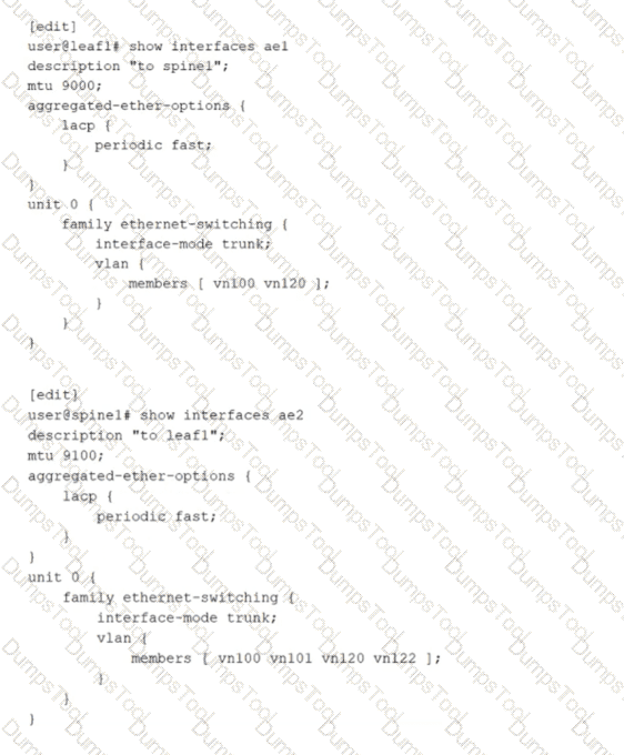
Referring to the exhibit, what is the problem?
The active statement must be added to LACP under the aggregated-ether-options hierarchy on one or both sides.
The ae interface numbers are not consistent.
The leaf-and-spine VLAN memberships are not consistent and should be changed to include the additional VLANs defined on spine1.
The leaf-and-spine MTUs are not consistent.
An aggregated Ethernet interface that uses LACP requires at least one side to actively initiate LACP negotiations. In the exhibit, both devices have LACP configured only with periodic fast, but neither side explicitly enables LACP active mode. When both ends operate in passive behavior, each side waits for the other to send LACP Data Units, and no negotiation begins. As a result, the LACP state does not progress to collecting and distributing, and the aggregated link fails to form as expected. Adding the active statement under the LACP hierarchy on one or both ends ensures that LACP frames are transmitted and the bundle can be negotiated and brought up.
The other options are not the root cause for bringing the bundle up. The aggregated Ethernet interface number does not need to match across devices because the bundle is locally significant on each system. VLAN membership differences on a trunk do not prevent LACP from establishing the aggregate; they only affect which tagged VLANs are allowed to pass once the link is operational. MTU differences can cause data plane issues such as fragmentation or drops for jumbo frames, but they do not typically prevent LACP formation because control frames are small and the physical link can still come up.
A switch receives an Ethernet frame that contains source and destination MAC addresses that are not in the Ethernet switching table. In this scenario, which two actions does the switch perform? Choose two.
The switch floods the frame out every port in the broadcast domain except the ingress port.
The switch adds the source MAC address to the Ethernet switching table.
The switch drops the frame.
The switch forwards the frame to the Routing Engine.
On Junos-based Ethernet switching platforms used in data centers, Layer 2 forwarding is handled primarily in the forwarding plane. When a switch receives a frame, it first performs source MAC learning. If the source MAC address is not already present in the Ethernet switching table for that VLAN or bridge domain, the switch creates a new entry that maps the source MAC to the ingress interface and the associated VLAN context. This learning step is fundamental to building the MAC table dynamically and enables efficient forwarding for subsequent frames destined back to that source.
Next, the switch attempts to forward the frame based on the destination MAC lookup in the same VLAN or bridge domain. Because the destination MAC is also not in the Ethernet switching table, the frame is treated as an unknown unicast. The default behavior for unknown unicast in a Layer 2 broadcast domain is to flood the frame out all other interfaces that belong to that VLAN or bridge domain, excluding the ingress interface. Flooding ensures the frame has the best chance of reaching the correct destination host. When the destination responds, the switch then learns that MAC address as a source on the return traffic, allowing future traffic to be forwarded as known unicast instead of flooded.
The switch does not drop the frame by default, and it does not forward the frame to the Routing Engine because this is normal Layer 2 bridging behavior, not a control-plane routing decision.
Referring to the exhibit,

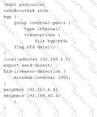
how much time must pass before a neighbor is considered down?
5000 ms
2000 ms
1000 ms
3000 ms
The exhibit shows BFD liveness detection configured under a BGP group with minimum-interval set to 1000 milliseconds. In Junos, BFD provides rapid failure detection by sending periodic BFD control packets between neighbors. The minimum-interval value is the negotiated minimum transmit and receive interval used for BFD control packets for that session. A neighbor is declared down when the local system fails to receive a certain number of consecutive BFD packets within the expected time window.
That time window is determined by the BFD detection time, which is calculated as the minimum-interval multiplied by the BFD multiplier. The multiplier represents how many BFD control packets can be missed before the session is considered failed. If the multiplier is not explicitly configured, Junos uses the default multiplier value of 3. Therefore, with minimum-interval set to 1000 ms and the default multiplier of 3, the detection time becomes 3000 ms. After approximately 3 seconds without receiving the expected BFD control packets, the BFD session transitions to down and BGP can react by treating the associated peer as unreachable for fast convergence.
This behavior is commonly used in data center underlays and EVPN fabrics to reduce convergence time compared to relying only on BGP hold timers.
Exhibit:

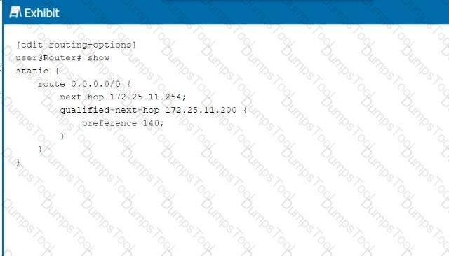
Referring to the exhibit, what is the route preference of the 172.25.11.254 next hop?
5
10
130
140
In the exhibit, we see two next-hop addresses for the default static route (0.0.0.0/0):
The first next hop is 172.25.11.254, with no specified preference.
The second next hop is 172.25.11.200, with a specified preference of 140.
Step-by-Step Breakdown:
Default Static Route Preference:If no preference is explicitly set for a next hop in Junos, it defaults to 5 for static routes.
Determining Preference:In this case, the next hop 172.25.11.254 does not have an explicit preference defined, so it will use the default value of 5. The second next hop has a preference of 140, which is higher, meaning it will only be used if the primary next hop is unavailable.
Juniper Reference:
Static Route Preference: In Junos, the default preference for static routes is 5, and this value is applied unless overridden by the preference parameter.
You are creating an IP fabric underlay and want to use OSPF as your routing protocol.
In this scenario, which statement is correct?
All leaf devices must be configured in separate OSPF areas.
All leaf and spine devices must be the same model to ensure the proper load-balancing behavior.
Interface speeds should be the same throughout the fabric to ensure that all links are utilized.
All spine devices must use the same router ID.
When creating an IP fabric underlay using OSPF as the routing protocol, consistent interface speeds are important to ensure optimal traffic distribution and utilization of all links.
Step-by-Step Breakdown:
OSPF and Interface Speeds:OSPF calculates the cost of a link based on its bandwidth. The default cost calculation in OSPF is:

If interface speeds vary significantly, OSPF may choose paths with lower cost (higher bandwidth), resulting in some links being underutilized.
Equal Utilization:To ensure that all links are equally utilized in an IP fabric, it is recommended to maintain uniform interface speeds across the fabric. This ensures balanced load sharing across all available paths.
Juniper Reference:
IP Fabric with OSPF: Juniper recommends consistent interface speeds to maintain even traffic distribution and optimal link utilization in IP fabric underlay designs.
How does a Layer 2 switch create an Ethernet switching table? Choose one.
It records the source MAC address of the received frames.
It downloads the table from the root bridge of the STP domain.
It uses a Layer 2 firewall filter.
It records the destination MAC address of the received frames.
A Layer 2 switch builds its Ethernet switching table through a learning process based on the source MAC addresses of incoming frames. When a frame arrives on an interface within a VLAN or bridge domain, the switch examines the source MAC address and associates it with the ingress interface and VLAN context. If the MAC address is new, the switch creates a new entry; if it already exists but is seen on a different interface, the switch updates the entry to reflect the new location. This dynamic learning is fundamental to efficient unicast forwarding and is why option A is correct.
Once the switch has learned MAC-to-port mappings, it can forward subsequent frames destined to those MAC addresses as known unicast out the specific egress interface rather than flooding them. If the destination MAC is unknown, the switch typically floods the frame within the VLAN or bridge domain to discover the correct destination. When the destination replies, the switch learns that MAC as a source, completing the learning cycle.
Spanning Tree Protocol does not provide a MAC table and there is no concept of downloading an Ethernet switching table from a root bridge. STP’s role is loop prevention and topology control at Layer 2, not MAC learning distribution. Firewall filters can enforce policy but do not create the switching table. Recording destination MAC addresses would not correctly learn endpoint locations because the destination can be unknown when the first frames are sent; source learning is reliable because every received frame carries the sender’s MAC address.
You want to enable routing between VLAN 10 and VLAN 20.

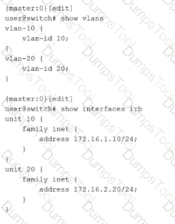
Which two configuration statements must be included in the configuration shown in the exhibit to accomplish this task? Choose two.
set vlans default vlan-id 20
set vlans vlan-10 l3-interface irb.10
set vlans vlan-20 l3-interface irb.20
set vlans default vlan-id 10
Inter-VLAN routing on Junos switching platforms is typically implemented by associating each VLAN or bridge domain with an IRB interface that provides the Layer 3 gateway for that VLAN. In the exhibit, VLAN 10 and VLAN 20 are defined with vlan-id values, and IRB logical units 10 and 20 already have IPv4 addresses assigned. However, the VLAN definitions do not yet reference the IRB interfaces. Without that association, hosts in the VLANs have no routed gateway on the switch, and the switch cannot perform Layer 3 forwarding between the two VLAN subnets.
To enable routing, each VLAN must include an l3-interface statement that binds the VLAN to the corresponding IRB logical unit. Adding l3-interface irb.10 under vlan-10 makes irb.10 the default gateway interface for VLAN 10 and enables the device to route traffic sourced from that VLAN. Adding l3-interface irb.20 under vlan-20 does the same for VLAN 20. Once both VLANs are bound to their IRB interfaces, the switch can route packets between 172.16.1.0/24 and 172.16.2.0/24 using its routing table, while still switching Layer 2 traffic within each VLAN.
The default VLAN settings are unrelated to enabling routing between these two specific VLANs. They control the behavior of the default VLAN, not the creation of Layer 3 gateways for VLAN 10 and VLAN 20.
What are three examples of martian addresses? Choose three.
224.0.0.0/4
172.36.0.0/24
192.0.0.0/24
198.60.0.0/16
127.0.0.0/8
In Junos routing and security contexts, martian addresses are IP prefixes that should not appear as valid, routable sources or destinations on normal interfaces because they are reserved, special-purpose, or otherwise not usable for general unicast forwarding. Treating these as invalid helps protect the control plane and prevents leakage of nonsensical routes into the fabric. This is especially relevant in data center underlays where strict routing hygiene is expected and where improper advertisements can cause blackholing or policy confusion.
The multicast range 224.0.0.0/4 is a classic martian example for unicast routing. These addresses are reserved for multicast and should not be accepted as ordinary unicast sources or carried as typical unicast reachability in an IP fabric. The loopback range 127.0.0.0/8 is also martian on physical networks because it is reserved for host self-reference and must never be forwarded by routers. Seeing it on an interface implies misconfiguration or spoofing.
The prefix 192.0.0.0/24 is reserved for special protocol and IETF assignments and is not intended for general use on public or private networks. As a result, it is commonly treated as martian in routing policy and input validation. By contrast, 172.36.0.0/24 and 198.60.0.0/16 are ordinary globally routable unicast space, so they are not martian by definition.
According to Juniper Networks, the bridge table is more commonly known as a _________.
forwarding table
forwarding bridge
bridging information table
forwarding information table
In Ethernet switching, the bridge table is the data structure that maps MAC addresses to the switch interfaces where those MAC addresses were learned. Juniper commonly describes this function as the Ethernet switching table and also refers to it as the forwarding table in Layer 2 contexts. The concept is the same: the switch learns source MAC addresses from incoming frames, associates them with an ingress port and VLAN or bridge domain, and then uses that learned information to forward future frames to the correct egress port as known unicast.
Calling it a forwarding table is accurate because its primary operational purpose is deciding how to forward Layer 2 frames efficiently. When a destination MAC is present in the table, the switch performs a unicast forward to the learned port. When a destination MAC is not present, the switch treats it as unknown unicast and floods it within the VLAN or bridge domain, while still learning the source MAC for future use.
The term forwarding information table is more strongly associated with Layer 3 routing, where a FIB represents resolved next hops for IP prefixes in the forwarding plane. That is a different structure than the Layer 2 bridge or MAC table. The other options are not standard Juniper terms for this function.
Verification sources from Juniper documentation
https://www.juniper.net/documentation/us/en/software/junos/multicast-l2/topics/topic-map/ethernet-switching-components.html
https://www.juniper.net/documentation/us/en/software/junos/multicast-l2/topics/concept/ethernet-switching-table-understanding.html
Which statement about the qualified next-hop feature is correct when configuring a static route?
Qualified next-hop is used for specifying redundant next-hops.
Qualified next-hop is used when the next-hop address is not within the route table of the local device.
Qualified next-hop is only required when a link-state protocol is configured.
Qualified next-hop uses pings to verify that the next hop is up.
Qualified next hop is the Junos mechanism that lets you configure more than one next hop for the same static route and control which one is preferred. This is most commonly used to build primary and backup forwarding behavior with deterministic selection. You configure a primary next hop and then add one or more qualified next hops with a different preference value. The route installs the best, lowest preference next hop as active, while keeping the alternate next hop available as standby. If the primary next hop becomes unusable, Junos can switch to the qualified next hop so traffic continues to flow.
This approach is widely used in data center edge and services routing, for example toward management networks, service appliances, or external gateways where you want a static default or summary route with predictable failover. It is not the same as resolving a non-directly-connected next hop. That scenario is handled by recursive resolution behavior, not by qualification. Qualified next hop also does not depend on any specific routing protocol, and it is not limited to link-state environments.
Finally, qualified next hop does not rely on sending pings to test reachability. Health tracking can be achieved through other mechanisms such as interface state, next hop resolution changes, or integration with failure detection features, but the qualified next hop feature itself is about preference-ranked redundancy for static routes.
What are two available modes when using LACP with an aggregated Ethernet bundle? Choose two.
aggressive
mixed
passive
active
On Junos devices used in data centers, an aggregated Ethernet bundle can run either static bundling or dynamic bundling using LACP. When LACP is used, Junos supports two negotiation modes: active and passive. These modes control whether the device initiates LACP negotiation by transmitting LACP Data Units or whether it waits to respond to LACP Data Units sent by its peer. In active mode, the system periodically sends LACP control frames to begin and maintain the negotiation. In passive mode, the system does not initiate negotiation but will respond if it receives LACP control frames from the neighbor.
From an operational perspective, active is typically recommended on at least one side of the link so the bundle reliably forms even if the peer is configured to be passive. If both ends are passive, each side waits for the other to start, and the aggregated link might not come up as expected. This is a common cause of down or partially formed bundles in leaf spine uplinks and server dual-homing scenarios.
Options aggressive and mixed are not Junos LACP modes for aggregated Ethernet. In Junos, you configure LACP under the aggregated-ether-options hierarchy and select active or passive behavior, along with optional timing such as periodic fast for quicker detection.
When using spine and leaf fabric architectures, what is the role of each device? (Choose two.)
Spine nodes are used for host connectivity.
Spine nodes are used for transit to other leaf nodes.
Leaf nodes are used for traffic to other leafs.
Leaf nodes are used for host connectivity.
In a spine-leaf fabric architecture, which is commonly used in data center designs, each device has a distinct role to ensure efficient and scalable network traffic flow.
Step-by-Step Breakdown:
Spine Nodes:
The spine nodes form the backbone of the fabric and are responsible for transit traffic between leaf nodes. They connect to every leaf switch and provide multiple paths for traffic between leaf nodes, ensuring redundancy and load balancing.
Leaf Nodes:
The leaf nodes are used for host connectivity. These switches connect to servers, storage, or edge routers. They also connect to the spine switches to reach other leaf switches.
Juniper Reference:
Spine-Leaf Architecture: In Juniper's IP fabric designs, spine switches handle inter-leaf communication, while leaf switches manage host and endpoint connectivity.
You are troubleshooting BGP routing and want to verify that you are sending a default route to peer address 10.100.25.6. Which command would satisfy the requirement?
show route protocol bgp 0.0.0.0
show route receive-protocol bgp 10.100.25.6 0.0.0.0
show route protocol static 0.0.0.0
show route advertising-protocol bgp 10.100.25.6 0.0.0.0
To confirm that your router is sending a specific route to a particular BGP neighbor, you must inspect the outbound advertisements toward that neighbor. In Junos, the command that shows routes being advertised to a peer is show route advertising-protocol bgp with the neighbor address specified. Adding 0.0.0.0 to the command filters the output to the default route, making it the most direct way to validate that the default route is actually being exported to peer 10.100.25.6. This is especially important in data center deployments where default route advertisement is often controlled by policy, conditional origination, or specific export terms, and where you want to verify the real operational result rather than just configuration intent.
The receive-protocol variant shows what you are learning from that neighbor, not what you are sending to it. The show route protocol bgp 0.0.0.0 command only confirms that the default route exists in your local routing table as a BGP-learned route, which does not prove it is being exported to the neighbor. The show route protocol static 0.0.0.0 command would confirm the presence of a static default route locally, but again it does not confirm that it is being advertised over BGP. Therefore, the outbound advertisement command is the correct verification method.
TESTED 28 Feb 2026
Copyright © 2014-2026 DumpsTool. All Rights Reserved