You want to make a widget appear on the main dashboard in Juniper Apstra. In this scenario, which statement is correct?
When creating the widget, select the Add to Blueprint Dashboard option.
On the blueprint dashboard, click on the Add Widget option.
Widgets automatically appear on the blueprint dashboard.
Set the Default toggle switch to On for the desired widget.
In Juniper Apstra, a widget is a graphical element that displays data from an intent-based analytics (IBA) probe. A widget can be used to monitor different aspects of the network and raise alerts to any anomalies. A widget can be viewed by itself or added to an analytics dashboard. A dashboard is a collection of widgets that can be customized and organized according to the user’s preference1.
The main dashboard in Juniper Apstra is the blueprint dashboard, which is the default view that shows the network information and configuration for the active blueprint. A blueprint is a logical representation of the network design and intent. The blueprint dashboard can display the system-generated dashboards, the user-generated dashboards, and the individual widgets that are relevant to the network2.
To make a widget appear on the main dashboard in Juniper Apstra, the user needs to set the Default toggle switch to On for the desired widget. This will add the widget to the blueprint dashboard, where it can be viewed along with other network information. The user can also remove the widget from the blueprint dashboard by setting the Default toggle switch to Off for the widget3. Therefore, the statement D is correct in this scenario.
The following three statements are incorrect in this scenario:
When creating the widget, select the Add to Blueprint Dashboard option. This is not true, because there is no such option when creating a widget in Juniper Apstra. The user can only select the widget type, the probe, and the display mode when creating a widget4. To add the widget to the blueprint dashboard, the user needs to set the Default toggle switch to On for the widget after creating it3.
On the blueprint dashboard, click on the Add Widget option. This is not true, because there is no such option on the blueprint dashboard in Juniper Apstra. The user can only view, edit, or delete the existing widgets and dashboards on the blueprint dashboard2. To add a widget to the blueprint dashboard, the user needs to set the Default toggle switch to On for the widget from the widgets table view3.
Widgets automatically appear on the blueprint dashboard. This is not true, because widgets do not automatically appear on the blueprint dashboard in Juniper Apstra. The user needs to manually add the widgets to the blueprint dashboard by setting the Default toggle switch to On for the widgets that they want to see on the blueprint dashboard3. The only exception is the widgets that are part of the system-generated dashboards, which are automatically created and added to the blueprint dashboard based on the state of the active blueprint2.
Which type of generic system should you select when adding a new server inside an existing rack type?
Internal generic
Rack generic
External generic
Embedded generic
In Apstra 5.1, servers that connect to leaf switches are represented as generic systems so Apstra can model links, apply connectivity templates, attach virtual networks, and validate intent. The selection of generic system type depends on whether the endpoint is considered part of the rack’s internal topology or an external attachment. When you add a new server inside an existing rack type, that server is treated as a component of the rack topology (that is, it lives “within” the rack alongside leaf switches and any other rack-internal endpoints). Apstra documentation refers to such systems as internal generic systems.
Internal generic systems are not managed like switches (no full device management), but they are first-class topology objects: they occupy ports on leaf switches, can be tagged with roles, and can be associated with link definitions that drive correct interface intent (LAG vs single link, VLAN tagging, and virtual network association). This modeling is essential in EVPN-VXLAN fabrics because correct endpoint attachment on leaf ports determines VLAN/VNI mapping and the resulting Junos v24.4 configuration rendered by Apstra.
External generic systems, by contrast, represent devices outside the rack topology (often used for external routers, firewalls, or other non-rack-contained endpoints). Because the question explicitly places the server inside an existing rack type, the correct choice is Internal generic.
Verified Juniper sources (URLs):
https://www.juniper.net/documentation/us/en/software/apstra5.1/apstra-user-guide/topics/topic-map/internal-generic-system-create.html
In Juniper Apstra terminology, to which network operating system concept does a routing zone refer?
IRB
VRF
VLAN
Access list
In Apstra 5.1, a routing zone is the primary construct used to represent an L3 domain for multitenant isolation. In traditional network operating system terms, that maps to a VRF (Virtual Routing and Forwarding instance). Each routing zone is placed “in its own VRF,” which provides independent routing tables and isolates IP traffic so that different tenants can reuse overlapping IP subnets without conflict. This is central to modern EVPN-VXLAN data center design, where tenants typically require clean separation of routing and policy boundaries.
Within a routing zone, you can create one or more virtual networks (often mapped to VXLAN segments) that provide L2 extension across racks while still being contained by the tenant’s VRF. If L3 gateway services are enabled for those virtual networks, their gateway interfaces (for example, IRB interfaces on Junos v24.4 leaf switches) are associated with the routing zone’s VRF so that inter-subnet routing occurs within the tenant boundary.
This terminology distinction is important: an IRB is an interface construct used to provide L3 gateway functionality for a VLAN/VXLAN segment; a VLAN is a Layer 2 segmentation mechanism; and an access list is a policy enforcement tool. A routing zone, however, defines the tenant’s L3 routing context, which is precisely what a VRF provides on Junos.
Verified Juniper sources (URLs):
https://www.juniper.net/documentation/us/en/software/apstra5.0/apstra-user-guide/topics/concept/routing-zones.html
https://www.juniper.net/documentation/us/en/software/apstra4.2/apstra-user-guide/topics/concept/routing-zones.html
You must enable ECMP load balance in your three-stage eBGP IP Clos fabric. In this scenario, which two features are required? (Choose two.)
A load-balance policy applied to the forwarding table
multipath multiple-as applied to the BGP group
A load-balance policy applied to the BGP group
multihop applied to the BGP group
In a three-stage eBGP IP Clos, a leaf typically learns the same prefix through multiple spines, and those spines are commonly in different AS numbers (a standard Clos pattern for simplified operations and fault isolation). To install multiple equal-cost eBGP paths for the same destination, Junos requires BGP multipath and, when the candidate paths come from different neighbor ASs, you must use the multiple-as capability (expressed as “multipath multiple-as” in many designs) to bypass the default same-neighbor-AS restriction for multipath selection. This ensures multiple eligible eBGP next-hops can be accepted as equal-cost paths and installed.
Separately, to actually perform load balancing in the forwarding plane across those installed next-hops, Junos uses a load-balancing policy that is applied to the forwarding table via routing-options forwarding-table export
A “load-balance policy applied to the BGP group” is not the required mechanism for ECMP forwarding behavior in this context, and multihop is unnecessary in a Clos underlay because neighbors are typically directly connected.
Verified Juniper sources (URLs):
https://www.juniper.net/documentation/us/en/software/junos/bgp/topics/topic-map/load-balancing-bgp-session.html
In Juniper Apstra, which statement about resources is correct?
User-defined resources are supported.
The scope of a pool is limited to a single blueprint.
The scope of a pool can be defined as global or blueprint specific.
Only the default resources are supported globally.
In Apstra 5.1, “resources” are the identifier values consumed by the fabric design and rendered into device configuration—examples include ASNs, IP addresses, VNIs, VLAN-related identifiers (where applicable), and similar allocation-driven values. These values are provided through resource pools, which are the authoritative containers Apstra draws from when assigning resources to blueprint roles (for example, leaf ASNs, spine ASNs, loopbacks, point-to-point subnets, and VNI ranges). A key architectural feature is that resource pools are not confined to one blueprint. Apstra supports pools with different scopes to match operational needs: some pools are managed centrally and reused across multiple blueprints, while other pools are created and used within the context of a specific blueprint when you want strict separation and lifecycle alignment with that blueprint.
This is why the correct statement is that a pool’s scope can be global or blueprint-specific. Global pools are appropriate when you want consistent allocation policy across fabrics (for example, enterprise-wide ASN ranges). Blueprint-specific pools are appropriate when you want per-fabric independence or when allocations are generated dynamically within the blueprint. This scope behavior is independent of Junos v24.4; Junos receives the final rendered values, but the pool scoping and allocation control are Apstra design-time constructs that ensure deterministic, conflict-free assignments at scale.
Verified Juniper sources (URLs):
https://www.juniper.net/documentation/us/en/software/apstra5.1/apstra-user-guide/topics/concept/resources.html
https://www.juniper.net/documentation/us/en/software/apstra5.1/apstra-user-guide/topics/concept/freeform-resource-management.html
https://www.juniper.net/documentation/us/en/software/apstra5.1/apstra-user-guide/topics/ref/resource-pools-api.html
Exhibit.
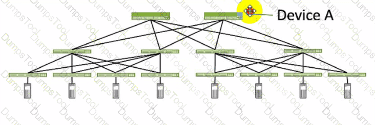
Referring to the exhibit, which role does Device A serve in an IP fabric?
leaf
spine
super spine
server
Device A serves as a spine in an IP fabric. An IP fabric is a network architecture that uses a spine-leaf topology to provide high performance, scalability, and reliability for data center networks. A spine-leaf topology consists of two layers of devices: spine devices and leaf devices. Spine devices are the core devices that interconnect all the leaf devices using equal-cost multipath (ECMP) routing. Leaf devices are the edge devices that connect to the servers, storage, or other network devices. In the exhibit, Device A is connected to four leaf devices using multiple links, which indicates that it is a spine device. The other options are incorrect because:
A. leaf is wrong because a leaf device is an edge device that connects to the servers, storage, or other network devices. In the exhibit, Device A is not connected to any servers, storage, or other network devices, but only to four leaf devices, which indicates that it is not a leaf device.
C. super spine is wrong because a super spine device is a higher-level device that interconnects multiple spine devices in a large-scale IP fabric. A super spine device is typically used when the number of leaf devices exceeds the port density of a single spine device. In the exhibit, Device A is not connected to any other spine devices, but only to four leaf devices, which indicates that it is not a super spine device.
D. server is wrong because a server device is a compute or storage device that connects to a leaf device in an IP fabric. A server device is typically the end host that provides or consumes data in the network. In the exhibit, Device A is not connected to any leaf devices, but only to four leaf devices, which indicates that it is not a server device. References:
IP Fabric Underlay Network Design and Implementation
IP Fabric Overview
IP Fabric Architecture
You are trying to deploy a five-stage template to a blueprint as shown in the exhibit. You cannot see your template name in the list of available templates.
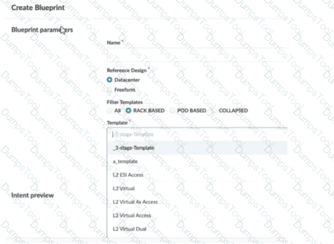
In this scenario, which statement is correct?
The Collapsed option should be selected.
You must include “five-stage” in the template name for it to appear in the list.
The Pod Based option should be selected.
Only Freeform-type blueprints support five-stage templates.
In Apstra 5.1, templates are organized by template type, and the Create Blueprint screen can filter the template list by those types. A five-stage Clos design in Apstra is represented as a pod-based template (multi-pod fabric with an additional tier such as super-spines to interconnect pods). Because of that, a five-stage template will only appear in the template selector when the Pod Based filter is chosen. If the filter is set to Rack Based or Collapsed, Apstra hides pod-based templates because those types correspond to different topology classes: rack-based aligns with a three-stage leaf–spine pod, while collapsed aligns with a spine-less topology pattern.
This behavior is by design to prevent selecting an incompatible template for the intended topology. The template name itself does not need to contain “five-stage”; Apstra determines its type from how the template was created and stored in the catalog. Also, five-stage templates are not limited to Freeform blueprints—five-stage is a data center fabric topology choice, and it is supported within the data center reference design workflows when the appropriate template type is selected.
So, to make the five-stage template visible and selectable, choose Pod Based in the template filter.
What is the purpose of an interface map in Juniper Apstra?
An interface map associates a logical device with a device profile.
An interface map specifies a connection between the interfaces of two devices.
An interface map specifies the number of ports and the port speeds of a logical device
An interface map specifies the connections between racks in a template.
According to the Juniper documentation1, an interface map is a configuration template that maps interfaces between logical devices and physical hardware devices (represented with device profiles) while adhering to vendor specifications. An interface map specifies a connection between the interfaces of two devices, such as a leaf and a spine, a leaf and a server, or a leaf and an external gateway. An interface map can also specify port transformations, such as breaking out a 40 GbE port into four 10 GbE ports, or disabling unused ports. An interface map can be used to achieve the intended network configuration rendering and to enable features such as LAG, ESI-LAG, or MLAG. Therefore, the correct answer is B. An interface map specifies a connection between the interfaces of two devices. References: Interface Maps (Datacenter Design)
You are asked to deploy a collapsed fabric architecture. Which two statements are correct about this deployment? (Choose two.)
All EVPN-VXLAN overlay functions are provided by the leaf devices.
Leaf devices are full-mesh connected.
Top-of-rack switches are full-mesh connected.
Top-of-rack switches provide VXLAN support.
In Apstra, a collapsed fabric (also described as “spineless”) consolidates traditional fabric tiers so that the primary fabric devices perform combined roles. Instead of a dedicated spine tier providing transit between leafs, the fabric is formed by leaf devices connected directly to each other using mesh links. This means a collapsed fabric uses a full-mesh topology at the leaf level, replacing the usual leaf-to-spine connections found in a three-stage Clos. Therefore, the statement that leaf devices are full-mesh connected is correct.
Because the collapsed fabric devices serve the fabric roles, they also provide the EVPN-VXLAN overlay functions (VTEP behavior, EVPN control-plane participation, and VXLAN encapsulation/decapsulation) necessary for tenant segmentation and service delivery. Juniper’s collapsed fabric validated designs further describe the collapsed fabric switches as serving all fabric roles (including border-leaf behaviors when external connectivity is required), reinforcing that overlay functions reside on these fabric leaf devices.
The remaining statements are not generally true for the collapsed fabric definition. Top-of-rack (access) switches—when present in certain collapsed designs—are not defined by default as full-mesh connected, and VXLAN support is not a requirement for those TOR/access switches unless the specific architecture explicitly uses them as VTEPs. The defining characteristics are the consolidated fabric roles and the leaf-level full-mesh.
Verified Juniper sources (URLs):
https://www.juniper.net/documentation/us/en/software/apstra5.0/apstra-user-guide/topics/concept/templates.html
https://www.juniper.net/documentation/us/en/software/apstra4.2/apstra-user-guide/topics/concept/rack-types.html
https://www.juniper.net/documentation/us/en/software/jvd/jvd-collapsed-dc-fabric-with-apstra/jvd-collapsed-dc-fabric-with-apstra.pdf
Using Juniper Apstra. which component is defined in a template?
the leaf-to-spine interconnection
the speed of the links between the spine devices and the leaf devices
the number of spine devices in a topology
the definition of IP pools
According to the Juniper documentation1, a template is a configuration template that defines a network’s policy intent and structure. A template can be either rack-based or pod-based, depending on the type and number of racks and pods in the network design. A template includes the following details:
Policies: These are the parameters that apply to the entire network, such as the overlay control protocol, the ASN allocation scheme, and the underlay type.
Structure: This is the physical layout of the network, such as the type and number of racks, pods, spines, and leaves. The structure also defines the leaf-to-spine interconnection, which is the number and type of links between the leaf and spine devices. The leaf-to-spine interconnection can be either single or dual, depending on the redundancy and bandwidth requirements.
Therefore, the correct answer is A. the leaf-to-spine interconnection. This is a component that is defined in a template, as it determines the physical connectivity of the network. The speed of the links, the number of spine devices, and the definition of IP pools are not components that are defined in a template, as they are either derived from the device profiles, the resource pools, or the blueprint settings. References: Templates Introduction | Apstra 4.2 | Juniper Networks
Exhibit.
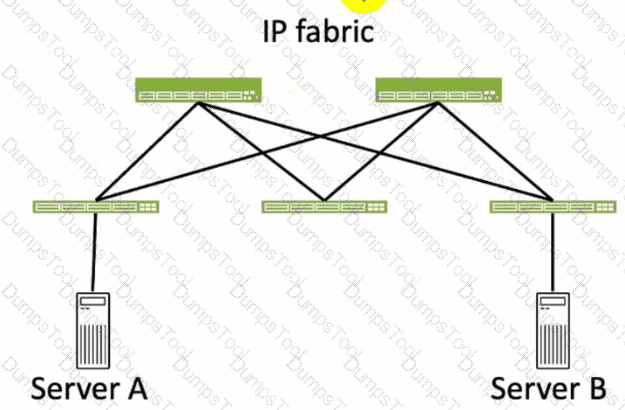
Referring to the exhibit, how many broadcast domains will an Ethernet frame pass through when traversing the IP fabric from Server A to Server B?
1
4
2
3
Referring to the exhibit, the image shows a simplified diagram of an IP fabric network connecting two servers, labeled as Server A and Server B. The IP fabric is a network architecture that uses a Clos topology to provide high bandwidth, low latency, and scalability for data center networks. The IP fabric consists of spine and leaf devices that use BGP as the routing protocol and VXLAN as the overlay technology1.
A broadcast domain is a logical portion of a network where any device can directly transmit broadcast frames to other devices at the data link layer (OSI Layer 2). A broadcast frame is a frame that has a destination MAC address of all ones (FF:FF:FF:FF:FF:FF), which means that it is intended for all devices in the same broadcast domain. A broadcast domain is usually bounded by a router, which does not forward broadcast frames to other networks2.
In the exhibit, there are two broadcast domains that an Ethernet frame will pass through when traversing the IP fabric from Server A to Server B. The first broadcast domain is the one that contains Server A and the leaf device that it is connected to. The second broadcast domain is the one that contains Server B and the leaf device that it is connected to. The IP fabric itself is not a broadcast domain, because it uses IP routing and VXLAN encapsulation to transport the Ethernet frames over the Layer 3 network. Therefore, the statement C is correct in this scenario.
The following three statements are incorrect in this scenario:
A. 1. This is not true, because there are not one, but two broadcast domains that an Ethernet frame will pass through when traversing the IP fabric from Server A to Server B. The IP fabric itself is not a broadcast domain, because it uses IP routing and VXLAN encapsulation to transport the Ethernet frames over the Layer 3 network.
B. 4. This is not true, because there are not four, but two broadcast domains that an Ethernet frame will pass through when traversing the IP fabric from Server A to Server B. The spine devices and the leaf devices that are not connected to the servers are not part of the broadcast domains, because they use IP routing and VXLAN encapsulation to transport the Ethernet frames over the Layer 3 network.
D. 3. This is not true, because there are not three, but two broadcast domains that an Ethernet frame will pass through when traversing the IP fabric from Server A to Server B. The IP fabric itself is not a broadcast domain, because it uses IP routing and VXLAN encapsulation to transport the Ethernet frames over the Layer 3 network.
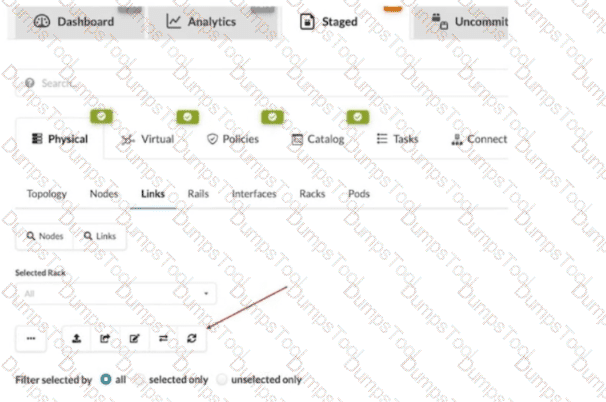
What does clicking the indicated icon shown in the exhibit accomplish?
It refreshes the screen.
It fetches the discovered Link Layer Discovery Protocol (LLDP) data.
It erases the entire cable map to start over.
It changes the speed of existing links.
In Apstra 5.1, the Staged > Physical > Links workspace is where you build and validate the cabling (link) intent for the fabric before committing changes. During deployment and day-0/1 build, Apstra can leverage LLDP neighbor discovery from the connected devices to accelerate and validate the cabling map. The indicated toolbar icon in the Links view is used to fetch discovered LLDP data from the devices so Apstra can compare the discovered neighbor relationships with the intended topology and, depending on workflow, help populate or validate link endpoints.
This is particularly important in leaf-spine IP fabrics because correct physical connectivity underpins the entire underlay—interface states, point-to-point addressing, and BGP sessions. In an EVPN-VXLAN design running Junos v24.4, broken or mis-cabled links quickly manifest as missing underlay adjacencies and failed EVPN control-plane signaling. Pulling LLDP discovery into Apstra helps you identify mismatches early (wrong neighbor, wrong port, missing neighbor) and reduces manual cabling errors.
This action is not merely a UI refresh, it does not wipe the cable map, and it does not modify link speeds. Its operational purpose is to import discovered LLDP neighbor information into the blueprint’s physical link view so Apstra can assist with accurate topology validation and deployment readiness.
Which two actions are required during Juniper Apstra's deploy phase? (Choose two.)
Assign device profiles to the blueprint.
Assign user roles to the blueprint.
Assign interlace maps to the blueprint.
Assign resources to the blueprint.
The deploy phase is the final step in the Juniper Apstra data center fabric design and deployment process. In this phase, you apply the Apstra-rendered configuration to the devices and verify the intent of the blueprint. Based on the web search results, we can infer the following actions are required during the deploy phase12:
Assign device profiles to the blueprint. This action associates a specific vendor model to each logical device in the blueprint. Device profiles contain extensive hardware model details, such as form factor, ASIC, CPU, RAM, ECMP limit, and supported features. Device profiles also define how configuration is generated, how telemetry commands are rendered, and how configuration is deployed on a device. Device profiles enable the Apstra system to render and deploy the configuration according to the Apstra Reference Design34.
Assign resources to the blueprint. This action allocates the physical devices, IP addresses, VLANs, and ASNs to the logical devices, networks, and routing zones in the blueprint. Resources can be assigned manually or automatically by the Apstra system. Assigning resources ensures that the blueprint has all the necessary elements to generate the configuration and deploy the fabric5 .
Assign user roles to the blueprint. This action is not required during the deploy phase. User roles are defined at the system level, not at the blueprint level. User roles determine the permissions and access levels of different users in the Apstra system. User roles can be system-defined or custom-defined .
Assign interface maps to the blueprint. This action is not required during the deploy phase. Interface maps are defined at the design phase, not at the deploy phase. Interface maps are objects that map the logical interfaces of a logical device to the physical interfaces of a device profile. Interface maps enable the Apstra system to generate the correct interface configuration for each device in the fabric . References:
Deploy
Deploy Device
Device Profiles
Juniper Device Profiles
Resources
What is the purpose of a Juniper Apstra rack?
It stores information on how pods connect to super spines.
It stores information on how leaf nodes connect to generic devices
It stores IP address and ASN pool information.
It stores device port data rates and vendor information.
A Juniper Apstra rack is a physical entity that contains one or more network devices, such as leaf nodes, access switches, or generic systems. A rack is used to organize and manage the network devices in the Apstra software application. A rack has the following characteristics:
It stores information on how leaf nodes connect to generic devices. This is because a rack can include generic systems, which are devices that are not managed by Juniper Apstra, but are connected to the network. A generic system can be a server, a firewall, a load balancer, or any other device that has a network interface. A rack stores the information on how the leaf nodes, which are the devices that provide access to the end hosts, connect to the generic devices, such as the port number, the link speed, the LAG mode, and the roles1.
It has a rack type, which defines the type and number of leaf devices, access switches, and/or generic systems that are used in the rack. A rack type is a resource that is created in the data center design phase, and it does not specify the vendor or the model of the devices. A rack type can be predefined or custom-made, and it can be used to create multiple racks with the same structure and configuration2.
It has a rack build, which assigns the specific vendor and model of the devices to the rack. A rack build is created in the staged phase, and it uses the rack type as a template. A rack build can also assign the resources, such as the IP addresses, the ASNs, and the VNIs, to the devices in the rack3.
It has a rack deployment, which applies the network configuration and services to the devices in the rack. A rack deployment is performed in the active phase, and it uses the rack build as a reference. A rack deployment can also monitor the network performance and compliance of the devices in the rack4.
The following three statements are incorrect in this scenario:
It stores information on how pods connect to super spines. This is not true, because a rack does not store any information on the pod or the super spine level of the network. A pod is a cluster of leaf and spine devices that form a 3-stage Clos topology, and a super spine is a device that connects multiple pods in a 5-stage Clos topology. A rack only stores information on the leaf and the access level of the network1.
It stores IP address and ASN pool information. This is not true, because a rack does not store any information on the IP address and ASN pools. IP address and ASN pools are resources that are created in the data center design phase, and they contain a range of IP addresses and ASNs that can be assigned to the devices and the virtual networks. A rack only uses the IP address and ASN pools to assign the resources to the devices in the rack build2.
It stores device port data rates and vendor information. This is not true, because a rack does not store any information on the device port data rates and vendor information. The device port data rates and vendor information are specified in the rack build, which assigns the specific vendor and model of the devices to the rack. A rack only uses the rack build to apply the network configuration and services to the devices in the rack deployment3.

TESTED 15 Jul 2026
Copyright © 2014-2026 DumpsTool. All Rights Reserved