Refer to exhibit.

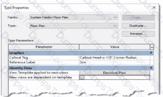
An electrical designer is reviewing the Type Properties for a floor plan view. How will the view behove when creating a new floor plan?
The Electrical Plan view template will be assigned to a new floor plan view created with the Floor Plan tool with the Floor Plan type selected
Creating a new floor plan view using the Floor Plan tool with the Floor Plan type selected will create a new Electrical Plan view template.
When duplicating a floor plan view of any type, the Electrical Plan view template will be assigned to the new floor plan view.
A new floor plan view created by duplicating a floor plan view of the Floor Plan type will be duplicated as a dependent view.
The exhibit shown displays the Type Properties dialog box for a System Family: Floor Plan view type. Within the “Identity Data” group, there are two critical parameters that govern the behavior of new views created from this view type:
“View Template applied to new views”
“New views are dependent on template”
According to Autodesk Revit’s documentation in the Revit MEP User’s Guide (Chapter 48 “Views and View Templates” and Chapter 49 “Preparing Construction Documents”):
“When a view template is assigned to a view type through the Type Properties dialog, any new view created from that view type automatically receives the defined view template. This ensures consistent visibility, graphics, and discipline settings for all new views.”
In this image, the parameter “View Template applied to new views” is set to Electrical Plan, and “New views are dependent on template” is checked. This means that any new floor plan created using this type will automatically have the Electrical Plan template applied, and the view will be dependent on that template, meaning it inherits all its visibility and annotation control settings.
This ensures that all electrical floor plan views generated are standardized and visually consistent, a fundamental practice in Revit Electrical Design workflows, as described in the Smithsonian Facilities Revit Template User’s Guide:
“Assigning a default view template to a view type (e.g., Electrical Plan) ensures every new view created follows organizational and graphical standards without manual setup.”
Option A matches this behavior exactly.
Option B is incorrect** because Revit does not create a new template automatically.
Option C is incorrect** because duplication of an existing view does not reassign templates by type.
Option D is incorrect** because dependent view creation requires a specific “Duplicate as Dependent” command, not this setting.
How can an electrical designer see changes from other users without saving their own work to the central model?
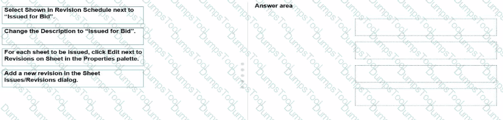
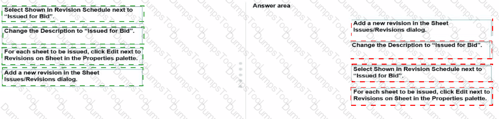
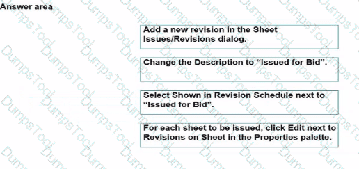
Relinquish All Mine
Reload Latest
Manage Worksets
Worksharing Display
In Autodesk Revit, particularly for electrical and MEP design disciplines using a workshared model, the command “Reload Latest” allows a designer to see changes made by other users without saving or publishing their own work to the central model. This tool ensures that while the designer continues to work locally, their environment stays updated with the latest modifications made by colleagues.
According to the Autodesk Revit MEP User Guide (Chapter 54 – Working in a Team), under the section Loading Updates from the Central Model, it states:
“As you work, you can see the changes other team members have made to the project after they have been synchronized with the central model. You can load updates from the central model without publishing your changes to the central model.
In your local file, click Collaborate tab ➤ Synchronize panel ➤ (Reload Latest).”
This confirms that the Reload Latest command refreshes your local file with any modifications from the central file that others have synchronized, but it does not send your local changes back. It is a critical feature for coordination in a team environment, especially when multiple designers—such as electrical, mechanical, and structural engineers—are contributing simultaneously to a shared BIM model.
By contrast:
A. Relinquish All Mine only releases ownership of elements but doesn’t update the local model.
C. Manage Worksets is for controlling visibility and editability of worksets.
D. Worksharing Display visually identifies ownership and status but doesn’t refresh model data.
Therefore, when an electrical designer needs to review updates from others (for example, when a lighting layout needs coordination with architectural ceiling adjustments), the proper workflow is to use Reload Latest, ensuring all new information from the central model appears instantly without saving or affecting their current unsaved edits.
Refer to exhibit.

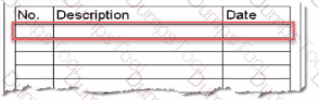
An electrical designer is issuing several sheets and wants 'Issued for Bid" to appear in the revision schedule of the title block. Drag and drop into the correct order to indicate how this can be accomplished to only the sheets that are being issued.


In Autodesk Revit Electrical Design, revisions are managed using the Sheet Issues/Revisions dialog to track changes and document issuance phases, such as “Issued for Bid” or “Issued for Construction.” The revision schedule on the title block automatically reflects this data when configured correctly.
According to the Revit MEP User’s Guide (Chapter 48 “Construction Documentation – Managing Sheets and Revisions”):
“Revisions define a record of changes issued with sheets. To display a revision in the title block, it must first be created in the Sheet Issues/Revisions dialog, assigned a description, and set to be shown in the revision schedule.”
Here’s how the process works step-by-step:
1️⃣ Add a new revision in the Sheet Issues/Revisions dialog.
Navigate to View tab → Sheet Composition panel → Revisions.
Add a new revision line entry (this creates a new revision record).
2️⃣ Change the Description to “Issued for Bid”.
In the same dialog, edit the Description field to reflect the issuance purpose.
3️⃣ Select Shown in Revision Schedule next to “Issued for Bid”.
Check “Show” in the Revision Schedule column so it will appear in the title block’s revision schedule table.
4️⃣ For each sheet to be issued, click Edit next to Revisions on Sheet in the Properties palette.
In the Properties palette, under Identity Data, click Revisions on Sheet → Edit and assign the “Issued for Bid” revision only to the sheets being released.
This ensures only the selected sheets display the “Issued for Bid” entry, maintaining proper control over which drawings are issued while others remain unaffected.
As described in the Smithsonian Facilities Revit Template User’s Guide:
“Revision schedules are dynamically linked to sheet issue data. Designers can show or hide revisions on a per-sheet basis by editing ‘Revisions on Sheet’ from the Properties palette.”
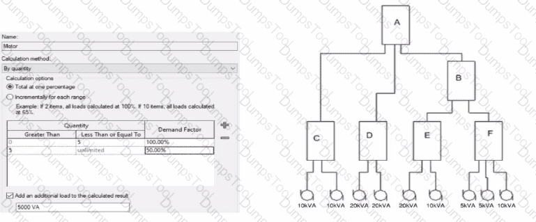
Refer to the exhibit.

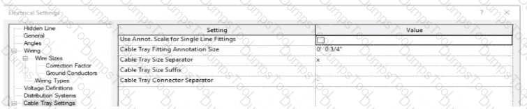
An electrical designer models a cable tray in a project and decides to check the box (or Use Annot. Scale tor Single Line Fittings and change the Cable Tray Fitting Annotation Size to 1/8" (3 mm).
What is the result?
(The image is presented m Imperial units: 1 In = 25 mm (Metric units rounded].)
All cable tray fittings in the project are changed per the new settings.
All cable tray fittings in the project change per the new settings when a views detail level is set to Fine.
New cable tray fittings use the new settings in views set to 1/8" (3 mm) scale.
New cable tray fittings use the new settings after the change.
In Autodesk Revit MEP, the Electrical Settings dialog box contains project-wide configuration parameters that affect all electrical systems, including Cable Tray Settings. This dialog allows users to control annotation scales, fitting symbols, and text size for documentation purposes.
The option labeled “Use Annot. Scale for Single Line Fittings” determines whether the cable tray fittings’ annotation graphics automatically scale according to the view’s annotation scale. When this box is checked, the annotation symbol size for fittings adjusts proportionally to the scale of the view.
Similarly, “Cable Tray Fitting Annotation Size” defines the annotation size for cable tray fittings in single-line representations (schematic views or simplified plan representations). Changing this parameter (for instance, from ¾” to ⅛”) modifies the visual representation globally for all cable tray fittings in the project, since the Electrical Settings dialog is a project-wide configuration, not a per-instance or per-view override.
According to the Autodesk Revit MEP User’s Guide (Electrical Systems – Cable Trays):
“Electrical settings define how cable trays and conduit are displayed throughout the project. Any change made to these settings, such as annotation size or use of annotation scaling, affects all related fittings and components in the project model.”
Therefore, once the designer checks the box for Use Annot. Scale for Single Line Fittings and changes the Cable Tray Fitting Annotation Size to 1/8” (3 mm), all cable tray fittings across the entire project will update to reflect these new settings.
An electrical designer has created a family and loaded It Into the project. The designer wants to connect the family to a power circuit but the Power icon is not available when the family Is selected.
How should the designer fix the problem?
Set the distribution system for the family.
Set the family parameter to Shared.
Change the Voltage parameter value to non-zero.
Add an electrical connector to the family.
In Revit Electrical Design, for a loadable family (such as electrical equipment, lighting fixtures, or devices) to connect to a power circuit, it must include an electrical connector defined in the Family Editor.
According to the Autodesk Revit MEP User’s Guide (Chapter 17 – Electrical Systems):
“For an electrical family to participate in a circuit, the family must contain an electrical connector. The connector defines the relationship between the component and the electrical system. Without a connector, Revit cannot establish a power connection, and the Power tool will not be available.”
— Revit MEP User’s Guide, Electrical Systems – Creating Electrical Families
The connector type determines what kind of system (Power, Data, Communication, etc.) the family can join. When the electrical connector is not added, Revit cannot recognize the family as part of an electrical system, and thus the Power icon is grayed out or unavailable.
Incorrect Options:
A. Set the distribution system for the family – only available after a connector is added.
B. Set the family parameter to Shared – allows tagging or scheduling across projects but does not affect connectivity.
C. Change the Voltage parameter value – affects circuit data but not connection availability.
Therefore, the issue is resolved only by adding an electrical connector in the Family Editor.
Verified References:
Autodesk Revit MEP User’s Guide (2011) – Electrical Systems → Creating Electrical Families → Adding Connectors
Revit Electrical Design Fundamentals Workbook – “Electrical connectors define the interface between components and electrical systems.”
Refer to exhibit.
(The Image is presented in Imperial units: 1 In = 25 mm [Metric units rounded).)

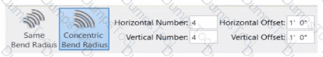
What is the electrical designer trying to do as shown in the exhibit?
Add Cable Tray
Place Parallel Conduits
Array Conduit
Place Multiple Pipe
The exhibit shown in the image is taken directly from the Revit MEP Electrical Systems workspace, specifically from the Parallel Conduits command interface. This dialog box appears when the designer activates the Place Parallel Conduits tool in the Systems tab → Electrical panel → Conduit dropdown → Parallel Conduits.
In this interface, the designer can specify:
Horizontal Number / Offset – defines how many conduits will be created horizontally and their spacing.
Vertical Number / Offset – defines how many conduits will be created vertically and their spacing.
Bend Radius Options:
Same Bend Radius – all conduits use identical bend radii.
Concentric Bend Radius – conduits bend concentrically around a common center point.
According to Autodesk’s Revit MEP 2011 User’s Guide (Chapter 18, Electrical Systems – Conduit Layout):
“The Parallel Conduits tool allows you to create multiple conduits side-by-side at the same time.
You can specify the number of conduits horizontally and vertically, as well as the offset between them.
You can also define whether bends have the same bend radius or concentric bend radii.”
— Revit MEP User’s Guide, Electrical Systems, Section: Conduit Layout
This tool is used when electrical designers need to route groups of conduits that run in parallel—such as power and data conduits running between panels or equipment racks.
The Concentric Bend Radius option (as shown in the exhibit) ensures all conduit bends share a common center, which is critical for maintaining uniformity in conduit sweeps and avoiding clashes during coordination.
Therefore:
A. Add Cable Tray – incorrect; the cable tray tool is separate and does not use bend radius options.
C. Array Conduit – incorrect; arraying is a different geometric function not specific to conduit routing.
D. Place Multiple Pipe – incorrect; applies to mechanical piping systems, not electrical conduits.
The display of Concentric Bend Radius, Horizontal Number, Vertical Number, and Offset confirms that the designer is using the Parallel Conduit placement tool.
Verified Reference Extracts from Revit Electrical Design Documentation:
Autodesk Revit MEP User’s Guide (2011) – Electrical Systems → Conduit Layout → “Parallel Conduits Tool” description.
Autodesk Revit MEP Training Curriculum – Electrical Module, Exercise 6.3 “Placing Parallel Conduits,” which illustrates the same interface for bend radius configuration.
Refer to exhibit.
(The image is presented in Imperial units: 1 In = 25 mm (Metric units rounded).)

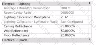
In the space properties for the space, the Lighting Calculation Luminaire Plane is Not Computed. What is causing this issue?
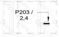
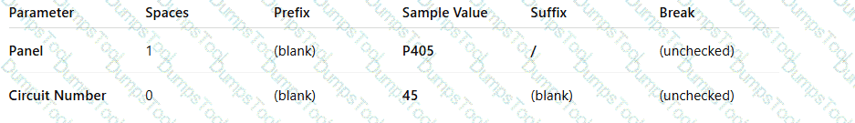
The lighting fixtures are missing an IES file.
No lights are placed in the space.
The lights in this space are not circuited.
Lights are at different elevations in the same space.
The parameter “Lighting Calculation Luminaire Plane: Not Computed” in the Space Properties dialog appears when Revit cannot perform a lighting calculation because no valid lighting fixtures are present within that defined space.
According to the Autodesk Revit MEP User’s Guide (Chapter: Spaces and Lighting Analysis):
“Lighting calculations are performed based on the luminaire data available in the space. If no light fixtures are present, the parameter ‘Lighting Calculation Luminaire Plane’ displays as ‘Not Computed’. Revit requires at least one hosted or ceiling-mounted lighting fixture with a valid light source to calculate illumination.”
In this case, although the space has defined reflectance values (ceiling, wall, and floor) and a lighting calculation workplane height (2’-6”), Revit cannot compute the Luminaire Plane because the software has no lighting geometry to reference for the photometric analysis.
Explanation of incorrect options:
A. Missing IES file: This would cause inaccurate photometric output, but not “Not Computed.”
C. Lights not circuited: Circuiting affects load summaries, not lighting calculations.
D. Lights at different elevations: Revit still computes the average luminaire plane even with varied fixture heights.
Thus, the lighting calculation is not computed simply because no lighting fixtures are placed in the space.
Refer to exhibit.

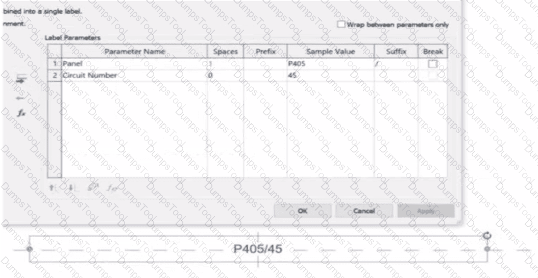
An electrical designer is working on an Electrical Device Panel-Circuit tag. The designer tags a receptacle using the tag properties shown in the exhibit The receptacle is assigned to panel P203 and circuit 2.4.
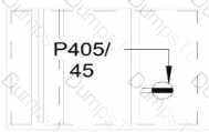
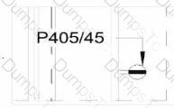
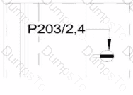
Which option shows the correct tag?
A)

B)

C)

D)

Option A
Option B
Option C
Option D
In the exhibit, the Label Parameters for the electrical device tag are configured as follows:
A white background with black text
AI-generated content may be incorrect.
This setup determines how the tag will display in Revit when applied to any device. Specifically:
The Panel parameter (P203 in this case) will be shown first.
A “/” separator follows because it’s assigned as the suffix for the Panel parameter.
The Circuit Number (2,4) is displayed immediately after the slash, with no extra spaces or line breaks.
Since the Break column is unchecked, the values will appear on one continuous line, not split across lines.
Revit documentation for tag creation confirms this behavior:
“When defining label parameters in a tag family, the Prefix and Suffix fields control text that appears before or after the parameter value, while the Break checkbox controls whether the text wraps to a new line.”
Therefore, when the tag is applied to a receptacle on panel P203 and circuit 2,4, the final formatted text will be:
P203/2,4
This corresponds exactly to option B, where the panel and circuit appear on the same line separated by a slash, with no spaces or line breaks.
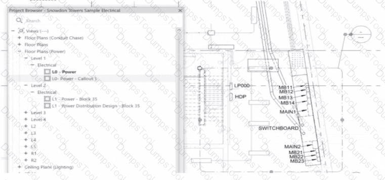
An electrical designer is working on a project with multiple buildings. The designer wants to organize the Project Browser by building For example, all views related to Building A will be sorted under Building A. and all views related to Building B will be sorted under Building B.
The designer decides to create a new parameter, assign it to views, and then sort the Project Browser according to the new parameter.
Which parameter should the designer use?
A reporting parameter
A global parameter
A project parameter
A family parameter
In Autodesk Revit, Project Parameters are used to add custom fields that apply to multiple elements within a specific project file — such as views, sheets, or schedules. These parameters allow project teams to categorize, group, and sort information within the Project Browser or within schedules without editing families or external files.
As defined in the Revit MEP User’s Guide and Revit Structure Parameters Chapter:
“Project parameters are specific to a single project file. Information stored in project parameters cannot be shared with other projects. A project parameter can be used, for example, to categorize views within a project.”
This statement directly confirms that project parameters are the correct tool for sorting or grouping views in the Project Browser.
To organize elements (like views or sheets) by building, the designer can create a custom project parameter named “Building” and assign it to the View category. Once assigned, the parameter values (e.g., “Building A” or “Building B”) can be filled in for each view.
The Smithsonian Facilities Revit Template Guide further supports this:
“View purpose is a Revit project parameter, providing a means for users to organize the many views that may exist in a BIM.”
Thus, using a project parameter allows users to add a “Building” field to each view, enabling customized browser organization (e.g., group views by Building A, Building B, etc.) without requiring shared parameters or family editing.
Refer to exhibits.

What is the demand load on Panel B?
65kVA
55kVA
30kVA
40kVA
In Revit Electrical, Demand Factors are applied through Load Classifications to compute an Estimated Demand Load rather than simply summing connected loads. The documentation states: “You use demand factors to adjust the rating of the main service… Demand factors are assigned to load classifications, and load classifications are assigned to device connectors. The estimated load for a device is calculated by multiplying the load by the demand factor. … The panel schedule can also display the load for each load classification.”
In the exhibit’s Demand Factor definition (for the Motor classification), the Calculation method is By quantity with Total at one percentage selected. Two quantity ranges are defined: 0–5 items at 100% and 5–unlimited at 50%. An additional checkbox adds an extra fixed load of 5000 VA to the calculated result. (This follows Revit’s behavior of applying the selected demand factor to the connected load and then adding any specified additional load to the result for that classification.)
Panel B feeds only panels E and F. The connected motor loads downstream are:
Panel E: 20 kVA + 10 kVA = 30 kVA
Panel F: 5 kVA + 5 kVA + 10 kVA = 20 kVA
Total connected motor load on B = 30 + 20 = 50 kVA (five items).
Because five items fall in the 0–5 range at 100%, the demand factor is 100% → 50 kVA. Per the definition, add an additional load of 5000 VA (5 kVA) to the calculated result:
Demand Load on Panel B = 50 kVA × 100% + 5 kVA = 55 kVA.
Therefore, the correct choice is 55 kVA.
Refer to exhibits.

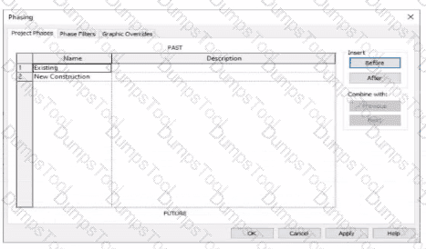
An electrical designer models an existing receptacle on an existing wall that the architect has indicated to be demolished.

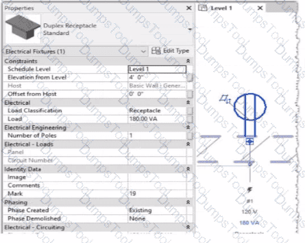
The view is intended to show demolition, and the view's Phase is set to New Construction. How should the designer indicate that the receptacle must also be demolished?
Add a Demolition phase, then set the receptacle parameter Phase Demolished to Demolition.
Set the receptacle parameter Phase Demolished to Demolition.
Set the receptacle parameter Phase Demolished to New Construction.
Set the receptacle's type parameter Match Phasing to Host.
In Autodesk Revit, phasing allows designers to track existing, demolished, and new elements across different project stages. Every model element includes two key phasing parameters:
Phase Created — defines when the element was built or introduced.
Phase Demolished — defines when the element is removed or demolished.
In the provided exhibits:
The project contains two phases: Existing and New Construction.
The receptacle’s Phase Created parameter is set to Existing, indicating it belongs to the pre-existing building condition.
The architectural wall hosting the receptacle is to be demolished during New Construction.
When a view’s Phase is set to New Construction and its Phase Filter is configured to show demolition, only elements whose Phase Demolished equals New Construction will appear as to be demolished. Therefore, the electrical designer must set the receptacle’s Phase Demolished value to New Construction so that it graphically displays as a demolished element in the demolition plan.
As explained in the Autodesk Revit MEP User’s Guide – Phasing and Coordination:
“Elements created in one phase and demolished in a subsequent phase must have their ‘Phase Demolished’ parameter set to that later phase to display properly in demolition views.”
Thus, to correctly coordinate with the demolition of its host wall, the receptacle must be flagged for demolition during New Construction.
Exhibit.

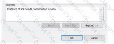
An electrical designer is working within a workshared electrical model The designer reloads the linked architectural model and receives the message as shown in the exhibit What does this message indicate?
There is a new interference with the architectural model.
There is a new coordination message within the architectural model.
An elements host within the architectural model has changed.
A monitored element in the architectural model has changed.
The warning message shown — “Instance of link needs Coordination Review” — appears when Revit detects a modification in a monitored element within a linked model, typically during a coordination workflow between architectural and MEP (electrical, mechanical, plumbing) disciplines.
According to the Revit MEP User’s Guide (Chapter 46 “Copy/Monitor and Coordination Review”):
“When a monitored element changes in the linked model, Revit displays a warning message indicating that the instance of the link needs Coordination Review. You can use the Coordination Review tool to accept, reject, or postpone the change.”
This mechanism ensures synchronization between linked models. For example, if the architectural ceiling or wall that hosts electrical elements (such as lighting fixtures or devices) is modified, moved, or deleted, Revit triggers this alert in the workshared MEP model.
The Smithsonian Facilities Template Guide further emphasizes:
“Coordination Review identifies monitored elements whose hosts or geometry have changed in a linked model. The designer must review these to maintain design consistency.”
Hence, the warning does not indicate a clash or interference (Option A), nor a coordination message created manually in the architectural model (Option B), but specifically a change in a monitored element in the linked architectural model (Option D).
Refer to exhibit.

Select the callout and choose a detail view under Reference Other View.
Select the callout and change its type from the Type Selector.
Delete the existing callout and create a new one with the correct type.
Open the callout view from the Project Browser and change its type.
In Autodesk Revit, when an electrical designer creates a callout view, the software automatically generates a new dependent or independent view based on the selected callout type. However, if a callout is accidentally linked to the wrong or redundant view, the designer can easily reassign it to another existing view without recreating the callout. This can be done using the Reference Other View property in the Properties palette.
According to the Revit MEP User’s Guide (Chapter 47 “Views and Callouts”):
“To link a callout to an existing view rather than creating a new one, select the callout, and under the properties for that element, use Reference Other View to specify the desired target view.”
This means that when the designer selects the callout (in this case, shown as “L0 - Power - Callout 1” in the Project Browser), they can modify the Reference Other View setting from the Properties palette to point to a different, pre-existing detail view or callout view—for example, one showing an enlarged power distribution layout or switchboard detail.
This is the most efficient workflow because:
It avoids recreating or redrawing the callout (unlike Option C).
It preserves all annotation and sheet referencing data.
It ensures alignment and consistency across sheet references.
The Smithsonian Facilities Revit Template User’s Guide reinforces this standard Revit practice:
“When a view reference or callout is incorrectly associated, use the Reference Other View property to redirect the annotation to an existing detail or dependent view.”
Why the Other Options Are Incorrect:
B. Change its type from the Type Selector: Callout types control annotation style (not the referenced view).
C. Delete and recreate: This is unnecessary and inefficient.
D. Open the callout view and change its type: Callout type cannot be changed directly once created; it’s controlled by view properties.
Therefore, the correct and Revit-recommended approach is Option A: Select the callout and choose a detail view under Reference Other View.
TESTED 14 Dec 2025
Copyright © 2014-2025 DumpsTool. All Rights Reserved