[Exhibit]

Click the Exhibit button.
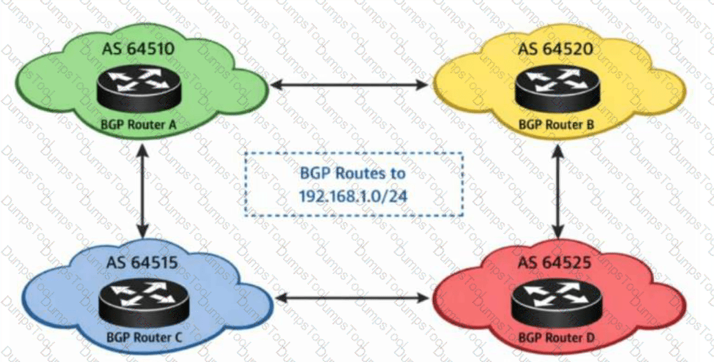
A network includes several autonomous systems that exchange routing information using BGP. Multiple BGP routes exist for the same prefix.
Referring to the exhibit, which attribute would BGP use first when selecting a preferred route?
local preference
AS path length
origin type
MED
The Junos BGP path selection algorithm proceeds through a strict, ordered sequence of comparison steps, and once next-hop reachability and route preference (administrative distance) have been confirmed as equal, local preference is the very first BGP-specific path attribute evaluated in the decision process. A route carrying a higher local preference value is always chosen over a competing route to the same prefix with a lower local preference, and this comparison takes absolute precedence over every subsequent attribute in the algorithm; if local preference values differ between candidate paths, the selection process concludes at this step without ever needing to examine AS path length, origin type, or MED at all. Only when two or more competing paths share an identical local preference value does the algorithm proceed to its third step, comparing AS path length and preferring the shortest, and only after a further tie does it move on to origin type (preferring IGP-origin over EGP-origin, and EGP-origin over incomplete), followed by MED comparison (preferring the lowest value, and only among routes learned from the same neighboring AS by default). Because local preference is evaluated strictly before all three of the other listed attributes, it is the attribute BGP consults first among the choices given, making it the deciding factor in scenarios such as this exhibit where multiple autonomous systems advertise competing paths toward the same 192.168.1.0/24 prefix. Reference topics: Junos Enterprise Routing – BGP, Understanding BGP Path Selection Order.
Which two statements are true about routing instances on Junos devices? (Choose two.)
A user-configured virtual-router instance type is used for non-VPN-related applications.
A user-configured virtual-router instance type is used for Layer 2 and Layer 3 VPNs.
A user-configured routing instance automatically generates a new routing table.
A user-configured routing instance automatically uses the master inet.0 table unless configured otherwise.
The virtual-router routing-instance type in Junos is a general-purpose instance type intended for creating isolated, independent routing and forwarding contexts within a single physical device for applications that have nothing to do with MPLS-based VPN services — common use cases include multi-tenant network segmentation, filter-based forwarding deployments, and simple traffic isolation between departments or customers on a shared switch or router, all of which are non-VPN-related applications by nature. Layer 2 and Layer 3 VPN services, by contrast, rely on a different, dedicated routing-instance type specifically named vrf, which integrates with MPLS/BGP-based VPN signaling, route distinguishers, route targets, and PE-CE routing exchange; virtual-router instances do not participate in that VPN signaling framework at all, which is why the statement associating virtual-router with VPN use is incorrect. Whenever an administrator creates any user-configured routing instance — regardless of its specific type — Junos automatically allocates and generates a brand-new, dedicated routing table for that instance, named according to the pattern instance-name.inet.0 (or the appropriate address-family suffix), which is entirely separate from and independent of the default master inet.0 table used by the global/default routing context. Because each new routing instance receives its own distinct table rather than sharing or defaulting into the master inet.0 table, the statement claiming instances automatically fall back to using inet.0 unless configured otherwise is factually incorrect; instances are isolated by design from the outset. Reference topics: Junos Enterprise Routing – Protocol Independent Routing, Routing Instance Types and Table Allocation.
You need to configure a Juniper Networks EX Series Switch to be able to accept both tagged and untagged traffic on the same access port.
Which feature will allow you to accomplish this task?
default VLAN
native VLAN
IRB interface
voice VLAN
Voice VLAN is the Junos feature specifically designed to allow a single access port to simultaneously handle two distinct traffic streams: untagged data traffic from a PC or workstation using the port's normal access VLAN, and separately tagged voice traffic generated by an IP telephone that is typically daisy-chained between the switch port and the connected PC. When voice VLAN is configured on an access interface, the switch instructs the attached IP phone (commonly via LLDP-MED) which VLAN ID to tag its voice traffic with, and the switch is then able to correctly classify and prioritize that tagged voice traffic into its designated voice VLAN while simultaneously continuing to treat any untagged frames arriving on that same physical port as belonging to the port's regular, untagged access VLAN — precisely satisfying the requirement to accept both tagged and untagged traffic together on one access port. Native VLAN, by contrast, is a trunk-port-only concept that designates which VLAN untagged frames on a trunk should be associated with; it has no applicability to an access port and does not enable simultaneous tagged traffic acceptance there. Default VLAN simply refers to the VLAN an interface belongs to absent other configuration and carries no dual-traffic capability. IRB interfaces provide Layer 3 gateway functionality for a VLAN and are unrelated to how tagged versus untagged frames are accepted at Layer 2 on a given physical port. Reference topics: Junos Enterprise Switching – VLANs, Configuring Voice VLAN on Access Interfaces.
You have configured a GRE tunnel from your local router with tunnel source 10.0.0.1 to a remote router at destination 192.168.0.1. The tunnel is functioning until you commit set routing-options static route 0.0.0.0/0 next-hop gr-0/0/0. This configuration causes the tunnel to go down.
Which statement is correct in this scenario?
A GRE interface cannot be used as a next hop for a static route.
The destination IP was being resolved using the default route, which now points to the tunnel itself.
A GRE interface must use the loopback as its source address to be used as a default route.
The tunnel destination must be resolved by a /32 host route.
A GRE tunnel's outer, delivery-layer packets are forwarded using the router's ordinary underlay routing table, meaning the tunnel destination address (192.168.0.1 in this case) must itself be resolvable to a physical, non-tunnel next hop for the encapsulated packets to actually leave the router. Before this configuration change, the default route (or some more specific route) presumably pointed toward a real physical next hop, allowing the router to reach 192.168.0.1 and keep the tunnel operational. When the administrator commits a static default route of 0.0.0.0/0 with a next hop of gr-0/0/0, every destination lookup that previously fell back to the default route — including the lookup for the tunnel's own destination address, 192.168.0.1, since no more specific route exists for it — now recurses through the GRE interface itself. This creates a circular dependency: the router needs to route to 192.168.0.1 to keep the tunnel up, but the only route it has to reach 192.168.0.1 now points back into the tunnel that requires 192.168.0.1 to already be reachable, so the interface's next-hop resolution fails and the tunnel drops. This is an entirely valid and common GRE design pitfall rather than any platform restriction; GRE interfaces can be legitimately used as static route next hops, do not require loopback-sourced encapsulation, and do not require a /32 host route to resolve their destination, provided that route does not recursively point back through the tunnel. Reference topics: Junos Enterprise Routing – Tunneling, Route Recursion and GRE Tunnel Destination Resolution.
You are required to ensure that Switch 1 will always be designated as the root bridge when participating in your switched network.
What do you need to do to satisfy this requirement?
Ensure Switch 1 has the highest system MAC address.
Ensure Switch1 has the lowest bridge priority of all the other switches.
Ensure Switch1 has the lowest port priority of all other switches.
Ensure Switch1 has the highest port costs of all the other switches.
Because root bridge election is decided primarily by comparing bridge priority values — with the switch advertising the numerically lowest priority always winning, and MAC address serving only as a fallback tiebreaker when priorities are tied — the only deterministic, reliable way to guarantee that a specific switch is elected root regardless of any other switch's hardware characteristics is to explicitly configure that switch with a lower bridge priority than every other participating switch in the topology. Relying on MAC address alone, as the first distractor suggests, is fundamentally unreliable: MAC addresses are burned in at the factory, cannot be predicted or controlled by the administrator, and any future hardware replacement or newly introduced switch with a numerically lower MAC address could unexpectedly seize the root role since MAC comparison only comes into play at equal priority in the first place, meaning a 'highest MAC' strategy does not even align with how the tiebreak actually favors the lowest value. Port priority and port cost are entirely separate STP parameters that influence which port on a non-root switch is selected as its root port, or which port is selected as designated versus blocking on a given segment; neither parameter has any bearing whatsoever on which switch is elected root bridge for the whole topology, since that decision is made purely from the Bridge ID comparison, independent of any per-port settings. Explicitly and deliberately lowering Switch 1's configured bridge priority is the only correct, industry-standard method. Reference topics: Junos Enterprise Switching – Spanning Tree Protocols, Guaranteeing Root Bridge Placement via Bridge Priority.
How does BGP prevent routing loops between internal peers?
It uses VRRP.
It uses AS path.
It uses BFD.
It uses a logical full mesh.
BGP employs two distinct loop-prevention mechanisms depending on whether peers are external or internal to the same autonomous system. Between external peers (EBGP), loop prevention relies on the AS path attribute: every time a route crosses an AS boundary, the local AS number is prepended to the path, and a router rejects any incoming route whose AS path already contains its own AS number, since that would indicate the route has looped back around. Between internal peers (IBGP) within the same AS, however, the AS path attribute never changes, because IBGP does not add AS numbers as routes are readvertised internally — meaning AS path alone cannot detect an internal loop. Instead, IBGP enforces a strict split-horizon-style rule: a router that learns a route via IBGP must never readvertise that route to another IBGP peer. This rule guarantees that every IBGP speaker within the AS must be directly peered with every other IBGP speaker (a logical full mesh) in order for all routers to receive all routes, since no IBGP router will relay IBGP-learned routes onward on another router's behalf. This full-mesh requirement is precisely why techniques such as route reflection and confederations were later developed — they preserve the same loop-prevention guarantee while relaxing the physical full-mesh peering burden. VRRP and BFD serve entirely unrelated purposes (gateway redundancy and fast failure detection, respectively) and play no role in BGP loop prevention. Reference topics: Junos Enterprise Routing – BGP, IBGP Split-Horizon and the Full-Mesh Requirement.
Which two statements are correct about BGP local preference? (Choose two.)
A local preference of 100 is the Junos default.
Local preference is advertised to EBGP peers.
Local preference is used to direct outbound traffic within an AS to a specific peer.
A local preference of 0 means to drop the route.
Local preference is a well-known, discretionary BGP path attribute carried exclusively in IBGP UPDATE messages, and Junos assigns every route a local preference value of 100 by default whenever a route is received without an explicit LOCAL_PREF value already attached, or when the attribute has not been otherwise modified through routing policy. This default of 100 becomes the implicit baseline against which any administrator-configured local preference adjustments are compared. Because higher local preference values are always preferred over lower ones during BGP best-path selection — and this evaluation happens before AS path length, origin, or MED are ever considered — network engineers commonly use local preference specifically to steer outbound traffic leaving the autonomous system toward a preferred exit peer or upstream provider, by assigning a higher local preference to routes learned from that preferred peer relative to routes learned from alternative peers, making the third statement correct as well. Local preference is explicitly excluded from advertisement to EBGP peers under the BGP specification; it is meaningful only within the boundaries of a single AS and is stripped before a route crosses an AS boundary outward, since a neighboring AS has no reason to trust or honor another organization's internal preference values. A local preference of 0 does not have any special 'drop' semantics in BGP — it is simply the lowest possible numeric preference value and is treated like any other value during comparison, not as a discard instruction. Reference topics: Junos Enterprise Routing – BGP, Local Preference Defaults and Outbound Traffic Engineering.
[Exhibit]

Click the Exhibit button.
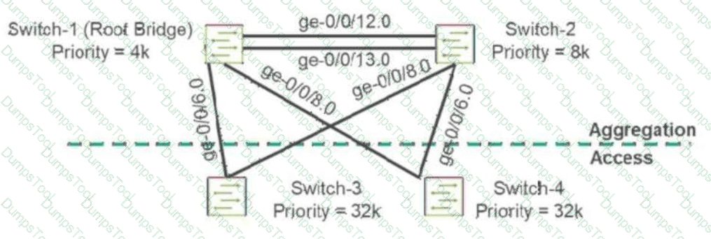
You are asked to ensure that there will not be any unwanted STP topology changes affecting your root bridge placement because a rogue switch was introduced into the network at the access layer.
Referring to the exhibit, which interfaces will need to have root protection applied to accomplish this task?
Place root protection on ge-0/0/6 and ge-0/0/8 on Switch-1 only.
Place root protection on ge-0/0/6 and ge-0/0/8 on Switch-3 and Switch-4.
Place root protection on ge-0/0/6 and ge-0/0/8 on Switch-1 and Switch-2.
Place root protection on ge-0/0/12 and ge-0/0/13 on Switch-1 and Switch-2.
Root protection (root guard) must always be applied on the ports of the switches you trust to remain root-bridge-eligible, specifically on the interfaces facing away from the legitimate root and toward parts of the network where an untrusted or rogue device could plausibly appear and begin transmitting superior BPDUs. In this topology, Switch-1 is the intended, permanent root bridge (lowest priority, 4k), and Switch-2 is its aggregation-layer peer; both sit above the access layer, where Switch-3 and Switch-4 connect downstream toward end-user-facing infrastructure and where an accidental or malicious rogue switch is realistically most likely to be introduced. The ge-0/0/6 and ge-0/0/8 interfaces on Switch-1 and Switch-2 are precisely the downlink ports facing that access layer, meaning they are the exact points at which a rogue switch's superior BPDU (one advertising a lower priority than the legitimate root) would first be received if such a device appeared beneath Switch-3 or Switch-4. Applying root protection on those specific interfaces causes Junos to immediately block (move to a root-inconsistent, discarding state) any port that receives a superior BPDU, preventing the rogue device from ever being accepted as root, while normal, non-superior BPDUs continue to be processed without disruption. Applying root guard on Switch-1 and Switch-2's peer link (ge-0/0/12/13) would be inappropriate, since that link legitimately connects two trusted, root-eligible switches. Reference topics: Junos Enterprise Switching – Spanning Tree Protocols, Root Protection Placement Strategy.
[Exhibit]

Click the Exhibit button.
Which three statements about this BGP session are correct? (Choose three.)
The export routing policy has been processed.
The routes are active.
The routes are stored in the default routing instance.
The routes originate from an external AS.
R1 modifies the BGP next hop.
The show route advertising-protocol bgp command displays exactly what would be transmitted to a specific BGP neighbor after all configured export routing policy has already been evaluated and applied, meaning any prefixes shown in this output have successfully passed through the export policy chain — confirming the export routing policy has been processed. The command header explicitly states '7 destinations, 7 routes (7 active, ...)' and every listed prefix is preceded by an asterisk, Junos's standard marker for an active route, confirming all seven displayed routes are active in the local routing table. The routing table name shown, XYZ.inet.0, indicates these routes reside in a named routing instance called XYZ rather than the default master routing instance, whose table would instead be labeled simply inet.0; this rules out the statement claiming the routes belong to the default instance. The AS path column shows only the origin code 'I' (IGP) with no AS numbers prepended ahead of it, meaning the AS path is empty, which indicates these prefixes were originated locally within R1's own AS (through redistribution or local origination) rather than having been learned from and passed through an external AS, ruling out that statement as well. Finally, the Nexthop column explicitly shows 'Self' for every route rather than an actual peer or learned address, confirming R1 is rewriting the next-hop attribute to its own address before advertising — a deliberate next-hop-self policy action typically applied toward IBGP peers. Reference topics: Junos Enterprise Routing – BGP, Verifying Advertised Routes and Export Policy Effects.
What are three valid OSPF adjacency states? (Choose three.)
reject
loading
down
established
init
OSPF neighbor state progression, as defined in RFC 2328 and displayed by Junos through show ospf neighbor, moves through a well-defined set of named states: Down, Attempt, Init, 2-Way, ExStart, Exchange, Loading, and Full. Down is the initial state, indicating no Hello packets have been recently received from a potential neighbor on that interface; it is a genuine, valid OSPF state and is correctly included here. Init indicates that a Hello packet has been received from the neighbor, but that neighbor has not yet listed the local router's own router ID within its Hello packet, so bidirectional communication has not yet been confirmed; this too is a standard, valid state. Loading occurs after the Exchange state, during which Database Description packets have been fully exchanged and the router is now actively requesting the specific, more-detailed LSAs it identified as missing or outdated from its neighbor via Link State Request packets; it is likewise a standard, valid OSPF neighbor state. 'Established' is not an OSPF state at all — that terminology belongs to BGP's finite state machine, where Established represents the fully operational session state; the OSPF equivalent concept is instead called Full. 'Reject' is not a recognized OSPF neighbor state under any circumstance and does not appear anywhere in the RFC 2328 state machine, making it an invalid distractor as well. Reference topics: Junos Enterprise Routing – OSPF, The OSPF Neighbor State Machine.
Which IS-IS TLV should be used to advertise information about the router's neighbors and link metrics?
TLV 22
TLV 2
TLV 132
TLV 129
TLV 22, the Extended IS Reachability TLV defined in RFC 5305, is the modern and Junos-preferred mechanism for advertising a router's adjacent neighbors together with the metric associated with each link. It carries the seven-octet system ID and pseudonode number of each neighbor along with a 24-bit wide metric field, and supports an extensible set of sub-TLVs used for traffic-engineering data such as interface and neighbor IP addresses, bandwidth, and administrative groups. The original IS Reachability TLV, TLV 2, defined in the base ISO 10589 standard, carries similar neighbor and metric information but is constrained to a 6-bit narrow metric with a maximum value of 63, which is inadequate for expressing meaningful cost differentiation in modern, high-capacity enterprise and service-provider topologies; consequently, Junos deployments are commonly configured for wide-metrics-only, favoring TLV 22 over the legacy TLV 2 whenever traffic-engineering-capable or simply more granular metric representation is desired. TLV 132, the IP Interface Address TLV, only advertises the IPv4 addresses configured on the originating router's interfaces and carries no neighbor-adjacency or metric information. TLV 129, the Protocols Supported TLV, merely lists which network-layer protocols (such as IPv4 or IPv6) the originating router is capable of routing, and likewise has nothing to do with neighbor reachability or link cost. Reference topics: Junos Enterprise Routing – IS-IS, Extended IS Reachability and Wide Metrics.
What are two characteristics of IS-IS? (Choose two.)
IS-IS is an interior gateway protocol.
IS-IS L1 routers route traffic between areas.
IS-IS routes use a default preference of 20.
IS-IS L1/L2 routers route traffic between areas.
IS-IS (Intermediate System to Intermediate System) was designed by ISO as a link-state Interior Gateway Protocol for routing within a single autonomous system, functioning on a hierarchical two-level model conceptually similar to OSPF's areas, which makes the first statement unambiguously correct. Within that hierarchy, Level 1 routers maintain detailed topology information only for their own local area and use a default route toward the nearest Level 2 or Level 1/Level 2 router to reach destinations outside the area; they explicitly do not carry inter-area topology information and therefore cannot route traffic between areas on their own. Routers that participate in both levels simultaneously — Level 1/Level 2 (L1/L2) routers — sit at the area boundary, maintaining a Level 1 database for their local area and a Level 2 database for the backbone, and it is specifically these dual-level routers that stitch inter-area traffic together, forwarding packets from the local area into the Level 2 backbone and vice versa, which confirms the second correct statement. Regarding route preference, Junos assigns distinct default preference (administrative distance) values of 15 for IS-IS Level 1 routes and 18 for IS-IS Level 2 routes — neither of which is 20 — so the preference-value statement is factually incorrect and included as a distractor testing precise knowledge of Junos default protocol preferences. Reference topics: Junos Enterprise Routing – IS-IS, Level 1, Level 2, and L1/L2 Router Roles; Default Route Preference Values.
[Exhibit]

Click the Exhibit button.
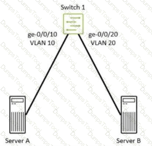
Referring to the exhibit, all possible firewall filters are configured along the path from Server A to Server B.
In which order will Switch 1 process transmit (Tx) and receive (Rx) firewall filters?
Rx-Port -- > Rx-VLAN -- > Rx-Router -- > Tx-Router -- > Tx-VLAN - > Tx-Port
Rx-Port -- > Rx-VLAN -- > Rx-Router -- > Tx-VLAN -- > Tx-Port
Rx-Port -- > Rx-VLAN -- > Tx-VLAN -- > Tx-Port
Rx-Port -- > Rx-Router -- > Tx-Router -- > Tx-Port
Because Server A resides in VLAN 10 and Server B resides in VLAN 20, traffic between them cannot remain a purely Layer 2 switched flow; it must be routed between the two VLANs, which on Switch 1 means the packet traverses the switch's internal routing engine (via an IRB interface) between the ingress and egress switching stages. Junos processes firewall filters along this path in a strict, layered order that mirrors the packet's actual journey through the device. First, any filter applied at the physical ingress port level (Rx-Port) is evaluated as the frame first arrives on ge-0/0/10. Next, any filter applied to the ingress VLAN (Rx-VLAN, i.e., VLAN 10) is evaluated as the frame is classified into its source broadcast domain. Because the destination subnet requires routing, the packet is then handed to the routing engine, where any input/ingress routed filter (Rx-Router) applied to the receiving IRB interface is evaluated next, followed by any output/egress routed filter (Tx-Router) applied as the now-routed packet is handed from the routing engine back out toward VLAN 20. Finally, the packet passes through any egress VLAN filter (Tx-VLAN, for VLAN 20) and then the egress physical port filter (Tx-Port) on ge-0/0/20 immediately before transmission to Server B. This complete six-stage sequence — Rx-Port, Rx-VLAN, Rx-Router, Tx-Router, Tx-VLAN, Tx-Port — reflects every filter-evaluation checkpoint a routed, inter-VLAN packet passes through on an EX Series Layer 3 switch. Reference topics: Junos Enterprise Switching – Layer 2 Switching and Firewall Filter Processing Order for Routed VLAN Traffic.
You are creating an aggregated Ethernet bundle using LACP on your Juniper Networks EX Series device.
In this scenario, which statement is correct?

LACP active mode is required on at least one side of the bundle.
You must use different LACP system priorities for each switch.
By default, LACP is in active mode on aggregated Ethernet interfaces.
LACP active mode is required on both sides of the bundle.
IEEE 802.3ad LACP defines two distinct negotiation modes, active and passive, and the standard's fundamental requirement for successful negotiation is that at least one end of the point-to-point link must be configured in active mode; an actively configured device initiates LACPDU transmission on its own, while a passively configured device waits and only responds once it receives an LACPDU from its peer. If both ends of the bundle were left in passive mode simultaneously, neither side would ever initiate the exchange, and no negotiation — and therefore no functioning aggregated bundle — would ever occur; at least one active participant is therefore mandatory, though having both sides active (active-active) is also fully valid and is in fact the most common production deployment. Junos does not enable LACP automatically on aggregated Ethernet interfaces; unlike some competing platforms, LACP must be explicitly configured under the aggregated-ether-options lacp hierarchy, and specifying no LACP configuration at all results in a 'static' LAG that relies purely on physical link-state rather than any protocol negotiation — there is no implicit default active mode. There is likewise no requirement to configure differing LACP system priority values between the two peer switches; system priority is used only to determine which side of the link controls port selection during negotiation and has no bearing on whether the bundle can form. Both sides being mandatorily active is a stricter requirement than the actual standard specifies. Reference topics: Junos Enterprise Switching – Link Aggregation, LACP Active and Passive Mode Negotiation.
TESTED 02 Sep 2026
Copyright © 2014-2026 DumpsTool. All Rights Reserved